Makers Blog

Dynamic Axiobus Configuration Totally IEC 61131

griboldi@phoenixcontact.com 30 March 2020 min. read
549 views 4 comments

This demo projects would like to be an easy way to implement an automatic startup of the Axioline configuration on the local bus of the PLC Next.

The project has been developed entirely in IEC 61131 to help developer who are not used to C++ or other HighLevel languages.

To do so I used the procedure for the bus startup found in Bus Conductor (https://github.com/PLCnext/BusConductor) and I trasposed it in IEC 61131.

Prerequisites

Libraries:

  • PLCnext Controller
    You should already find it in the default path for PLCNext Eng library (C:\Program Files\PHOENIX CONTACT\PLCnext Engineer 2020.0\Libraries) as it comes with the software installation.

The projects has been tested with:

  • PLCNext Engineer 2020.0.1
  • AXC F 2152 FW 2020

It is a normal PLCNext project, so you just need to know how to download a project with PLCNext Engineer 😉

Functionalites Description

In the project you will find 2 function blocks:

  • InitAxio
    It will simply startup the connected bus accepting the whole physical configuration.
  • InitAxio_AutoConfig
    It starts the configuration as the other block but it will give also the list of connected modules.

To get informations from the modules, I used PDI objects, please refer to the Axioline manual to get more informations about them.

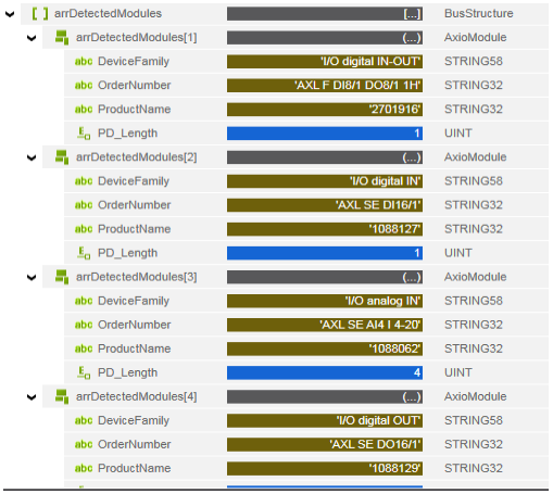
The information given by InitAxio_AutoConfig are:

  • DeviceFamily  [STRING58] -> The module type (analog/digital, input/output, others)
  • OrderNumber  [STRING32] -> The order number of the module
  • ProductName [STRING32] -> The product name of the module
  • PD_Length  [UINT] -> The number of words of Input process data of the module (Please consider that axioline modules have the same dimension for PDIN and PDOUT)

This properties has been choosen because I thought they could be the minimum information you may need for an easy use of the bus, however it is possible to add (or remove) properties reading the desired PDI object.

Example

Project Description

The project’s structure is quite simple

Project Structure

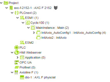
Software side, the project contains a single Cylic task (100ms) with the 2 available function blocks.
Please notice that both the blocks need to be used in a Cyclic Task.

Hardware side, you can see the dummy module AXL F physcial; this module is needed for the dynamic bus configuration.
It provides 2 arrays that contains all the process data produced and consumed by the modules.

Main Program

The Main program contains the two available function blocks

Main Program

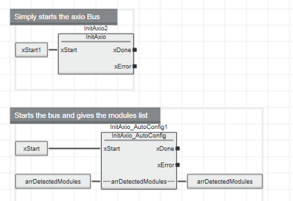
As you can see, there is no need of particular configuration to use these FBs.

Please noticed that you can use just one of them at one time.

InitAxio

The function block follow different phases

InitAxioPhases :

  1. Init
  2. ResetDriver
  3. CreateConfiguration
  4. ReadLocal_IO
  5. GetNumberOf_IO
  6. ReadUserConfiguration
  7. Load_PD_Mapping
  8. StartDataTransfer
  9. End

As already mentioned I copied these steps from C++ Bus Conductor library, they are the necessary steps for the Axiobus startup.

InitAxio_AutoConfig

This function block is quite the same of the previous one but it introduces a step before the End step:

InitAxioPhases :

  1. Init
  2. ResetDriver
  3. CreateConfiguration
  4. ReadLocal_IO
  5. GetNumberOf_IO
  6. ReadUserConfiguration
  7. Load_PD_Mapping
  8. StartDataTransfer
  9. ReadPhysicalConfiguration
  10. End

During the Step 9 the function block reads the properties of every module found in the configuration using PDI read commands.
Also the Step 9 is developed in phases to make it easier to modify.

Possibilities

The demo project provides just few tools that might help you to develope more articulated dynamic configurations.

You can for example compare the list of modules read with a desired configuration (for example simply looking at the product numbers) and then choose to prevent the use of all process datas or use just a part of them.

You can implement routines for dynamic configuration of connected modules (specially for analog modules).

Or you can use the process data length to dynamically change the dimension of a module (e.g. if you replace a 16DI with a 32DI module).

Or it can just help you to implement a dynamic bus configuration in your IEC 61131 project.

Repository

https://github.com/griboldi/Dynamic-Axiobus-Configuration

Note:

The Makers Blog shows applications and user stories of community members that are not tested or reviewed by Phoenix Contact. Use them at your own risk.

Discussion

Please login/register to comment

Login/Register

Leave a Reply

kmanieri 22.11.2021

Is it possible to update this library to include smart element IO?

Login / Register to reply
kmanieri 22.11.2021

Nevermind - it already does work with the Smart Elements! It was the RS485 Card that it did not like.

griboldi 23.11.2021

Hi, the library is not bind to a particular list of AXIO modules. It reads the bus and make it runs indipendently from the configuration. For this reason it should be compatible with all standard Axioline Modules. It will have problems with modules like AXC F IL ADAPT - 1020304 that has a particular behaviour.

Daniel.Skorka@zebotec.de 27.07.2023

Hello Gianluca, many thanks for making this available to us! I have just integrated into our software, where it will certainly save us a lot of headaches :-) I have two questions that I hope you might be able to answer: - With every module I have tested, it occupies exactly the same number of bytes in dio-1/ DI4096 as it does in dio-1 / DO4096, even if the data sheet for that module says that PDin and PDout are of different sizes - AXL F DI32/1 1F is an example. Do you know if we can expect all modules to behave that way? - When the module needs less process data space than it occupies, which bytes of the process data space are used and unused seems to be unpredictable. For example, AXL F DI16/1 DO8/2-2A 2 uses the left byte of two it occupies in DO4096, whereas AXL F DI8/1 DO8/1 1H uses the right byte of two in DO4096. Is there any logic to this? Best regards, Daniel

Login / Register to reply
Martin PLCnext Team 31.07.2023

Hi Daniel, I'm not sure if Gianluca has seen your comment, so I will try to answer your questions. Your questions are not specific to the application that Gianluca has described here; the questions relate to the behaviour of Axioline I/O modules in general, whether they are used with an AXC F controller, or an AXL F Bus Coupler. Q1 - "Do you know if we can expect all modules to behave that way?" - the answer is "yes". The Axioline specification has only one parameter for "Process Data Length" for each I/O module. It is not possible for an Axioline I/O module to specify different values for Input process data length and Output process data length. Q2 - "which bytes of the process data space are used and unused seems to be unpredictable." - the answer to this question is on page 101 of the Axioline F: system and installation user manual: "Axioline F devices have at least eight bits of process data. If less than eight bits are used, they occupy the least significant bits of the byte. The significance of the data corresponds to the Motorola format (Big Endian). The significance of the data bytes declines as the number goes up. For the process data assignment and the assignment of the process data to the terminal points of a module, please refer to the module-specific data sheet." If you have more technical support questions like this, I can recommend that you contact the technical specialists in your local Phoenix Contact office.

Martin BeePlanet Factory 21.12.2023

Hello, This demo project has been very useful for me. I have just one PLCnext project and I deploy it in many PLCs, some of them without any axioline modules connected and some others with a variety of modules connected to them. I have used the InitAxio and configured the AXL F physical module in my project and now I’m able to detect the modules and configure them online for my needs without changing the project. I have just one thing left that I didn’t get with the functions of the demo. In the PLCs that don’t have any axioline module connected I’m not able to configure the axioline. What I’m trying to do is to reset all the errors and avoid the error led and the errors that arise in the PLC when there isn’t any module connected to it. Is there any way to do it? Thank you, Martin

Login / Register to reply
Gianluca Riboldi 03.01.2024

Hello Martin, glad you appreciate this example. I updated it with the changes needed to make it works better without modules. You can find the V2 at the same link. Please try it and let me know if there are some problems with it. Best Regards Gianluca

Martin BeePlanet Factory 31.01.2024

Dear Gianluca, I have just implemented the new version in our project and now in the PLCs without modules the axioline gets ready (without any error). That’s exactly what I was missing in the first version. Thank you so much.

Login / Register to reply
Newsletter
Never miss a new article
Sign up for the newsletter
Never miss news about PLCnext Technology
Get interesting content via newsletter four times a year
Receive exclusive information before all other users