Function block for controller redundancy
Available with AXC F 2152 and AXC F 3152
This topic describes the redundancy feature for use with PLCnext Control AXC F 2152 or AXC F 3152 on an applicative base.
General concept

The communication between the two PLCs necessary for controller redundancy is realized via UDP/IP communication protocol.
For this purpose, the following rules for the assignment of the IP addresses must be considered:
- The ID addresses of the
FirstPLC andSecondPLC must use the same Net IDs. - The difference between the IP addresses of the First PLC and the Second PLC must be limited to the fourth octet only.
Example:
|
|
First PLC |
Second PLC |
|
IP Address Subnet Mask |
192.168.0.91 255.255.255.0 |
192.168.0.92 255.255.255.0 |
Prerequisites
From the PLCnext Store, download the ASR AXC F 2152 or the ASR AXC F 3152 function block library (free of charge) and import it into PLCnext Engineer on your computer. In the following
Function block ASR_ContrRed_2152
On the two PLCs the same program is in operation. Therefore, during run time of the program it is necessary to determine which PLC is the First controller and which PLC is the Second controller. For this purpose, the fourth octet of the IP addresses (host ID) of the First and of the Second controller needs to be stored as a constant at the corresponding input parameters of this function block in the PLCnext Engineer program.
During the start-up of the program, the own IP address is read out by executing a firmware service. As a result of the comparison of the own IP address with these constants, it can be determined whether the controller is the First or the Second PLC.
Only one controller (either First or Second) controls the process. The PLC which controls the process is the Primary, the other PLC has the role of the Backup. The determination which PLC is the Primary respectively the Backup is done by a comparison of the value of its own current state signals with the current state signals of the partner PLC.
Therefore, this function block compares cyclically the current state signals of the partner PLC (xPartnerSignal...) with its own current state signals (xSignal...). The values of the signals are compared in ascending order beginning with 0.
If a difference of the values at a determined bit number x is perceived the values of the current state signals with higher bit numbers (> x) are not compared anymore. Therefore, the priority of a switch-over condition depends on the bit number used for this current state signal.
Possible switch-over conditions are:
- Switching over the state of a PLC from
BackuptoPrimaryis carried out if the value of its own current state signal isTRUEand the value of the corresponding current state signal from the partner PLC isFALSE. - Switching over the state of a PLC from
PrimarytoBackupis carried out if the value of its own current state signal isFALSEand the value of the corresponding current state signal from the partner PLC isTRUE.

Description of inputs and outputs
|
Name |
Data type |
Data direction |
Description |
|
|
INT |
Input |
Fourth octet of the IP address of the |
|
|
INT |
Input |
Fourth octet of the IP address of the |
|
|
TIME |
Input |
Delay time for switching over the PLCs in case a switch-over condition occurs.[1] |
|
|
BOOL |
Input |
A rising edge at this input signal resets the |
|
|
BOOL |
Input |
With |
|
|
BOOL |
Input |
Current state signals: |
|
|
ASR_ARR_STR_1_50 |
Input |
|
|
|
BOOL |
Output |
Indicates whether the PLC is the First-PLC. |
|
|
BOOL |
Output |
Indicates whether the PLC is the Second-PLC. |
|
|
BOOL |
Output |
Indicates whether the PLC has the redundancy role Primary. |
|
|
BOOL |
Output |
Indicates whether the PLC has the redundancy role Backup. |
|
|
BOOL |
Output |
Indicates whether the partner PLC is the |
|
|
BOOL |
Output |
Indicates whether the partner PLC is the |
|
|
BOOL |
Output |
Indicates whether the partner PLC has the |
|
|
BOOL |
Output |
Indicates whether the partner PLC has the |
|
|
BOOL |
Output |
Current state signals of the partner PLC: |
|
|
STRING |
Output |
Own IP address. |
|
|
STRING |
Output |
IP address of the partner PLC. |
|
|
STRING |
Output |
Indicates time and date for the last switch-over of the PLC from |
|
|
BYTE |
Output |
Indicates the state of the signal when the last switch-over from |
|
|
BYTE |
Output |
Indicates the state of the signal from the partner PLC when the last switch-over from |
|
|
STRING |
Output |
Indicates time and date for the last switch-over of the PLC from |
|
|
BYTE |
Output |
Indicates the state of the signals, when the last switch-over from |
|
|
BYTE |
Output |
Indicates the state of the signals from the partner PLC when the last switch-over from |
|
|
DINT |
Output |
Maximum measured delay time for the transmission of the current state signals. This output parameter can be reset by a rising edge at the input signal |
|
|
BOOL |
Output |
This output indicates with a rising edge that an error has occurred. You can read the corresponding error codes at the output signals |
|
|
WORD |
Output |
Indicates the cause of the error. |
|
|
WORD |
Output |
Indicates additional information to the cause of the error. |
|
|
INT |
Output |
Indicates the current role of the PLC: 0: Undefined 1: Primary 2: Backup |
|
|
INT |
Output |
Indicates the status for the transmission of the current state signals: 0: Undefined 1: Transmission of the signals is OK 2: Transmission of the signals is not OK |
|
|
INT |
Output |
Number of switch-overs of the PLC from |
- The valid range for the value of the
tSwitchOverDelayinput parameter is between 300 ms and 1000 ms. The achievable switch-over time of the system depends on the following parameters of the overall application and therefore cannot be generalized:- the task interval in which this function block is used
- the overall CPU load of the PLC
- the Network Redundancy protocol which is used for the application specific network layout
For a task interval of 20 ms, the minimum value for thetSwitchOverDelayinput variable should be 300 ms.
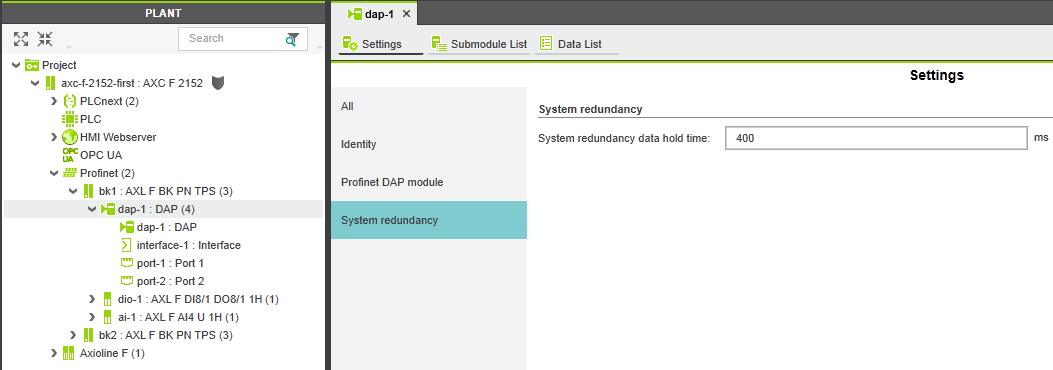
The switch-over time of the system must also be parameterized for the PROFINET IO devices. This is done with PLCnext Engineer at the settings of the DAP node via the System redundancy data hold time. The value entered here must not be lower than the switch-over time set at the function block.
Error Codes
|
Error Code |
Description |
|
C401 |
Indicates that an error while trying to stop the PROFINET ARs. |
|
C402 |
Indicates that an error while trying to start the PROFINET ARs. |
|
C403 |
Indicates that an error occurred while reading the adjustments of the IP address. The |
|
C404 |
Indicates that this PLC is neither the The |
|
C405 |
Indicates that during the start-up of the internal state machine a timeout occurred. The output parameter indicates the relevant step at which the timeout was detected. |
Additional program instances in the ESM
For the controller redundancy to work properly, the following program instances must be created in addition to the cyclic call of the function block:
- Program instance for the
Cold Startsystem event task:

- Program instance for the
Warm Startsystem event task:

- Program instance for the
Stopsystem event task :

Note: The watchdog of this system event task must be set to 2000 ms.
The ASR_ContrRed_2152 function block internally uses some firmware services. To make these services available, it is necessary to include the PLCnextBaseServices library into the PLCnext Engineer project, and to create a program instance of the ServiceProvider program into one cyclic task:


Recommendations for the configuration of the function block
arrAR_DevList InOut parameter
At start-up, the function block performs some PROFINET specific services on the PROFINET IO devices and therefore the function block needs to know the names of all connected IO devices. For this purpose, the “Name of Station” of all PROFINET IO-devices (bus couplers) must be stored at the arrAR_DevList InOut parameter:


In this example program, two PROFINET IO devices with the names “bk1” and “bk2” are used. If there are more IO devices connected their names must also be added to this list.
xSignal0 to xSignal7 input parameters
The switch-over conditions are defined by logical operations which are assigned to the xSignal0 to xSignal7 input parameters.
If there are no special requirements related to the switch-over conditions the following configuration is recommended in order to trigger a switch-over in case of “standard failure” situations, like switching off the power supply of a PLC, setting a PLC into Stop operating mode, or disconnecting the Ethernet connection:
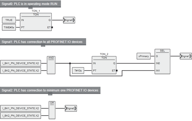
The I_BKx_PN_DEVICE_STATE variables are to be defined as External Variables and the responding Global Variables needs to be connected to the PN_DEVICE_STATE process data item of the PROFINET bus couplers.
In this example program, two bus couplers are used. If there are more bus couplers in the system, the AND and the OR function needs to be extended accordingly.
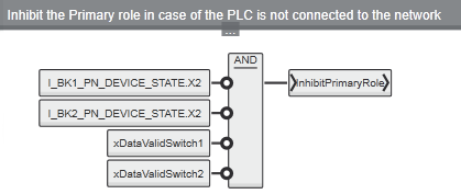
xInhibitPrimaryRole input parameter
This input parameter is used to prevent the PLC from taking over the Primary role. This is usually useful when the PLC has no connection to an Ethernet network at all. In this case the PLC doesn’t know the current status of the partner PLC and therefore it should not takeover the Primary role.
In the following example two bus couplers and two Ethernet switches are used in the system. Thus, if the controller has neither a connection to one of the bus couplers nor to one of the switches, it can be assumed that the controller is not connected to the network, and therefore the takeover of the Primary role would not make sense:
OPC UA variables
To make it possible to display the current status of the redundant controllers on a visualization system, the function block provides corresponding information in the form of OPC UA® variables via the embedded OPC UA® server on the PLCs.
|
Name |
Data type |
Description |
|
|
INT |
Indicates the current role of the PLC: 0: Undefined 1: 2: |
|
|
INT |
Number of switch-overs of the PLC from |
|
|
INT |
Indicates the status for the transmission of the Current-State-Signals: 0: Undefined 1: Transmission of the signals is OK 2: Transmission of the signals is not OK |
|
|
UINT |
Cycle counter for the “PLC in Run” monitoring. |
|
|
SINT |
Indicates the current role of the First PLC: 0: Undefined 1: 2: |
|
|
SINT |
Indicates the current state of the First PLC: 0: Undefined 1: 2: |
|
|
SINT |
Indicates the current role of the Second PLC: 0: Undefined 1: 2: |
|
|
SINT |
Indicates the current state of the Second PLC: 0: Undefined 1: 2: |
See also