In redundancy mode, the preset IP addresses are used as the system IP address of the respective Ethernet interface. The process-leading controller (= PRIMARY controller) can additionally be reached via the system IP address of the respective Ethernet interface.
You can only configure the system IP addresses of the Ethernet interfaces. The physical IP addresses of the controllers at the respective interface are set automatically based on the system IP address.
The automatic setting of the physical IP addresses is done by incrementing the last octet, according to the following scheme:
System IP address:
192.168.1.x (with x = 0 ... 252)
Physical IP address of the first controller (redundancy type "first"):
192.168.1.x+1
Physical IP address of the second controller (redundancy type "second"):
192.168.1.x+2
The following figure shows an example of the automatic setting of physical IP addresses which is based on a system IP address:
Exemplary IP addresses
Network
interface
Type of
IP address
First controller leads process
Second controller leads process
First/PRIMARY
Second/BACKUP
First/BACKUP
Second/PRIMARY
LAN1
Physical
192.168.1.11
192.168.1.12
192.168.1.11
192.168.1.12
System IP address
192.168.1.10 [1]
-
-
192.168.1.10 [1]
LAN2
Physical
192.168.2.11
192.168.2.12
192.168.2.11
192.168.2.12
System IP address
192.168.2.10 [1]
-
-
192.168.2.10 [1]
LAN3.1/3.2
Physical
192.168.3.11
192.168.3.12
192.168.3.11
192.168.3.12
System IP address
192.168.3.10 [1]
-
-
192.168.3.10 [1]
The process-leading controller (PRIMARY controller) can also be reached via the system IP address in addition to the physical IP address.
Configuring IP address settings
Configuration via Web-based Management
See the Configuration - NetworkWBM page.
The topic opens in a new browser window so you can view the above explanations and the WBM page description side by side.
Configuration via PLCnext Engineer
Note: In PLCnext Engineer only the PRIMARY controller is visible in the PLANT area. After you have successfully compiled and sent the project to the PRIMARY controller, the BACKUP controller is synchronized to the PRIMARY controller, meaning the project is automatically transferred from the PRIMARY to the BACKUP controller.
To open the settings, double-click the RFC 4072R node in the PLANT area.
↪ The editor group of the controller opens.
In the Settings tab, select the Ethernet view.
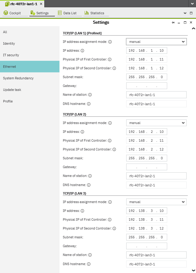
(Settings are already edited here)Show an exampleShow an example of a complete set of IP addresses for a redundant system of RFC 4072R.
The IP address settings depend on your station configuration:
Operating with two attached devices
If you are operating a redundant control system with two controllers, you need to set the (system) IP address at the respective Ethernet interface.
The physical IP addresses of the controllers at the corresponding Ethernet adapter (fields Physical IP of First controller and Physical IP of Second controller) are then set automatically based on the system IP address (IP address in the PLCnext Engineer user interface).
You can set the system IP addresses of the controllers either manually or automatically:
Set IP addresses automatically
In the IP address assignment mode drop-down list, select automatic.
↪ PLCnext Engineer assigns system IP addresses and physical IP addresses to both controllers from the configured IP address range, as soon as a connection to the PRIMARY controller is established.
Set IP addresses manually
In the IP address assignment mode drop-down list, select manual.
Enter the system IP address.
Note: You can't enter anything in the input fields Physical IP of First Controller and Physical IP of Second Controller.
These values are set automatically by PLCnext Engineer.
Enter the Subnet mask.
Enter the Gateway, but only for the respective Ethernet interface.
Security Note: Never assign a gateway for more than one Ethernet interface!
That can lead to uncontrolled sending of data via the Ethernet interfaces.
↪ PLCnext Engineer assigns the IP addresses to the controller as soon as a connection to the controller is established.
Operating with only one attached device
If you are temporarily operating with only one attached device (which is theSingleMode redundancy state), you need to set only the physical IP address at the respective Ethernet interface.
You can set the IP address of the controller either automatically or manually.
Set IP addresses automatically
In the IP address assignment mode drop-down list, select automatic.
↪ PLCnext Engineer automatically assigns a physical IP address from the configured IP address range, as soon as a connection to the controller is established.
Set IP addresses manually
In the IP address assignment mode drop-down list, select manual.
Enter the physicalIP address.
Note: In SingleMode, the Physical IP of FIRST controller and Physical IP of SECOND controller values are not relevant.
Enter the Subnet mask.
Enter the Gateway, but only for the respective Ethernet interface.
Security Note: Never assign a gateway for more than one Ethernet interface!
That can lead to uncontrolled sending of data via the Ethernet interfaces.
↪ PLCnext Engineer assigns the IP addresses to the controller as soon as a connection to the controller is established.


 Security Note: Never assign a gateway for more than one Ethernet interface!