Configuration - Network
Valid from firmware version 2021.6 up to 2024.6 - for firmware 2025.0 or newer, see WBM 2: Configuration - Network; for firmware 2020.3 to 2021.0 LTS see WBM: Information - Network configuration
Accessibility
|
The LAN Interface tab of this WBM page is accessible with these user roles:
Read-only:
|
The Netload Limiter tab of this WBM page is accessible with these user roles:
Read-only:
Read and reset statistics:
|
How to get into the WBMHow to get into the WBM
Establishing a connection to the Web-based Management (WBM):
- Open a web browser on your computer.
- In the address field, enter the URL https://<IP-address-of-the-controller>/wbm,
for example: https://192.168.1.10/wbm.
For further information, see WBM.
Network page
On the Network WBM page you can view or configure the LAN interface settings of your controller (depending on the user role).
From firmware release 2023.0 LTS, the Network WBM page contains a tab for configuring the Netload Limiter.
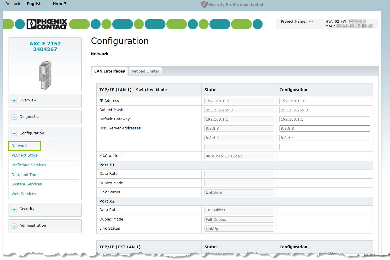
LAN Interfaces tab
For each Ethernet interface on the controller, this page lists the following information:
- Naming of a LAN interface in the form "TCP/IP (LAN <n>[1]) – Switched Mode[2]"
- IP Address
- Subnet Mask
- Default Gateway
- DNS Server Addresses
- MAC Address
- Naming of 1st physical port[3]
- Data Rate – can be 10 or 100 or 1000 Mbit/s (on LinkUp when link is active only)
- Duplex Mode – can be Full Duplex or Half Duplex (on LinkUp when link is active only)
- Link Status – can be LinkUp (a connection to another Ethernet device is established) or LinkDown (No connection to another Ethernet device is established)
- Naming of 2nd physical port[3]
- Data Rate
- Duplex Mode
- Link Status
- Naming of a LAN interface
- and so on...
The list continues for all Ethernet interfaces and their ports known to the controller.
- and so on...
- The naming for Ethernet interfaces on the controller itself has the form "LAN <n>", with the index corresponding to the naming of the interface on the controller's housing. If an extension module is attached (e.g. with Extension module AXC F XT ETH 1TX ), its Ethernet interface is named in the form "EXT LAN <n>".
- Only displayed for LAN interfaces with two ports.
- The naming form for physical ports depends on the controller type, e.g.:
- at AXC F 2152 it is "Port X1" and "Port X2"
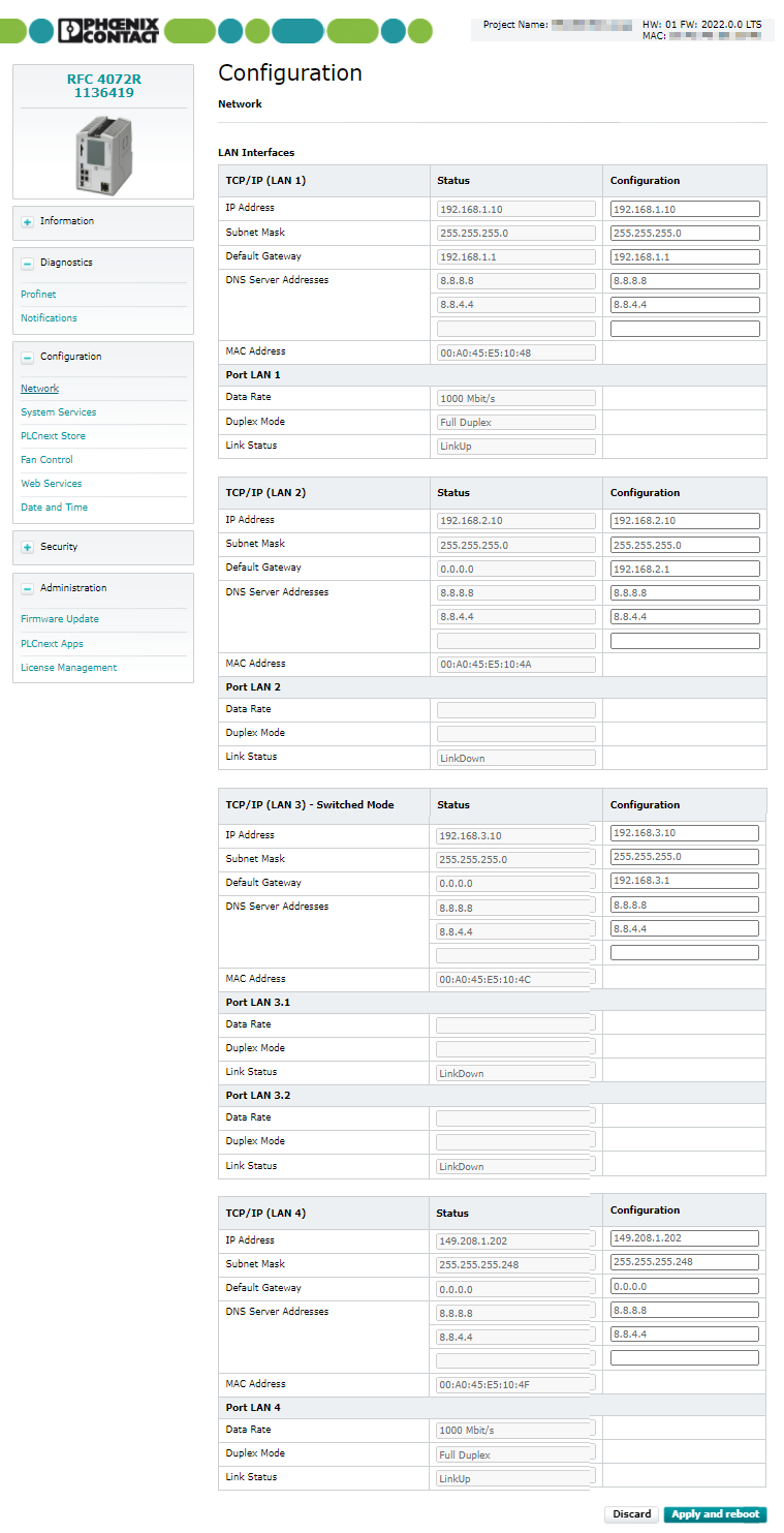
- at RFC 4072S it is "Port LAN 3.1" and "Port LAN 3.2"
- at AXC F XT ETH 1TX it is "Port X3 Extension Ethernet Port"
User role with read permissions
When you are logged in with a user role with read permissions only you can view the current network settings and status values in the column Status. Because you can't change anything, there a no other buttons visible in the page.

User role with write permissions
When you are logged in with the Admin or SecurityAdmin user role you can view the current network settings and status values in the column Status. You can change the current network settings in the Configuration column.
To change the network settings, proceed as follows:
- Enter the new settings in the Configuration column.
- Click to apply the new settings.
The new settings are sent to the controller. An automatic reboot of the controller is performed to activate the new settings.
Information on further network setting options can be found in the PLCnext Engineer Online Help. You can find the PLCnext Engineer Online Help in its menu Help → View Help.
Tip: Starting with release 2022.0 LTS, the PLCnext Engineer embedded help is also online available.

Changing IP addresses for a redundant control system
Available from firmware 2022.0 LTS on RFC 4072R
If you're working with a redundant control system, the configuration of IP addresses is different:
Even though you are working with two controllers, the IP address are set for the whole system. From there, the IP addresses for the controllers are derived. For details, see Structure of IP addresses for system redundancy with RFC 4072R.
To change the network settings of a redundant control system, proceed as follows:
- Enter the new settings in the Configuration column, which is set as the system IP address.
The physical IP addresses for the redundant controllers will be set automatically, incrementing the last octet of the address by 1 (for the First Controller) or by 2 (for the Second Controller). - Click to apply the new settings.
The new settings are sent to the controllers. An automatic reboot of the controllers is performed to activate the new settings.
Netload Limiter tab
Available from firmware release 2023.0 LTS
Prerequisite: The Netload Limiter is activated by means of the System Services WBM page.
The Netload Limiter offers an option to limit the CPU load caused by an increasing amount of Ethernet telegrams. For details see Netload Limiter. From firmware release 2023.0 LTS, settings for the Netload Limiter can be done via the Web-based Management, in addition to the pre-existing means for configuration (IEC 61131‑3 function block, RSC service, XML configuration file).
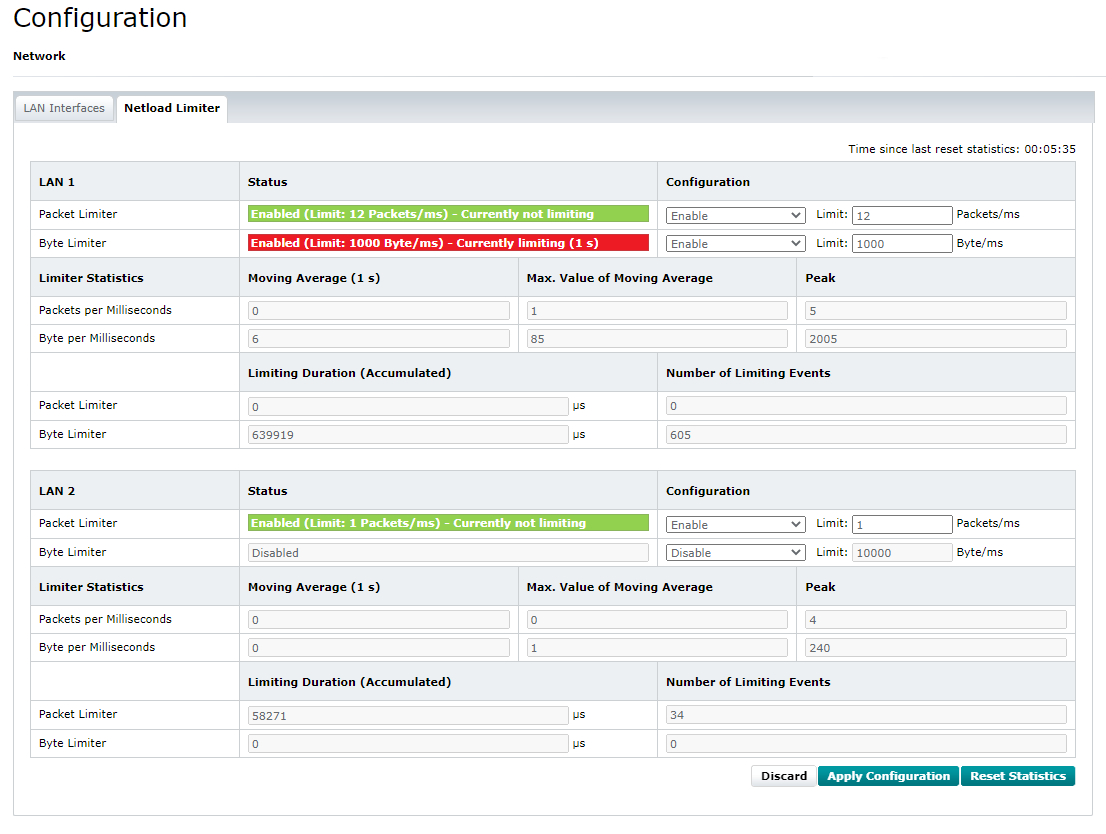
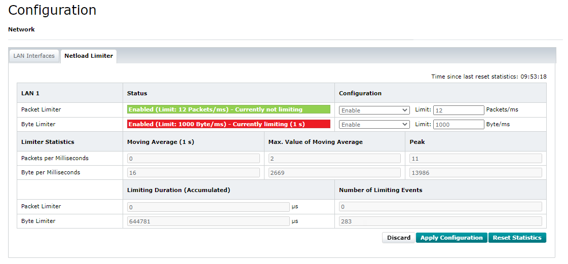
The Netload Limiter tab in the Network WBM page shows present configurations and statistics, allows to change configurations (depending on a user role with write permissions), and to reset the statistics. The handling is quite self-explanatory. After applying a different configuration of the Netload Limiter by means of the button, that configuration is active immediately. The controller does not need to be restarted. That allows for approaching cautiously to proper limits.
- The Time since last reset statistics counter in the upper-right corner of this WBM page shows the time that has elapsed since the last reset of the statistics.
- Statistics are always collected, even if no limiter is enabled.
- Statistics are not reset by applying a configuration change.
- The button resets the enabled packet and byte counters in this WBM page as well as the Time since last reset statistics time counter. It does not reset the controller. However, when resetting the controller, the enabled counters in this WBM page are restarting, too.
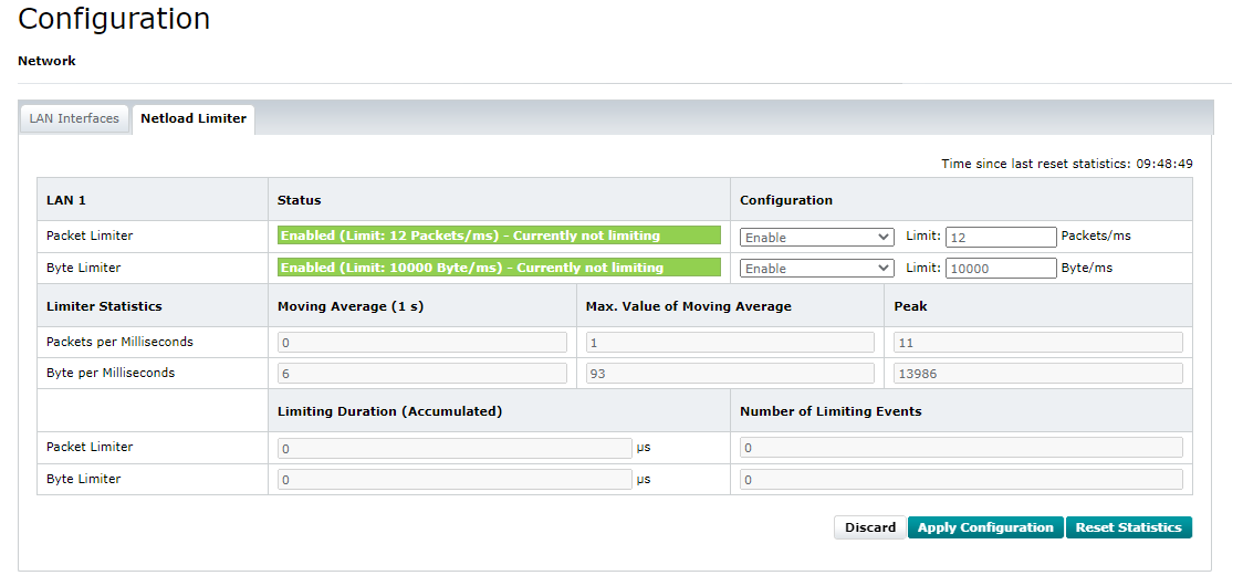
When the Packet Limiter or Byte Limiter is enabled but currently not limiting, the status is highlighted green :
When a limiter is enabled and currently limiting, the status shows a red marker for the limiter in question:
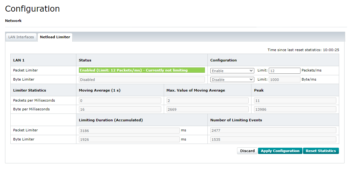
You can disable one limiter while leaving the other limiter enabled:
If you're using the AXC F 2152 with the left-aligned AXC F XT ETH 1TX Ethernet module (mandatory in the security context for network segmentation), it may look like this: