Starting up the AXC F XT PB PROFIBUS master
Available from 2022.0 LTS for AXC F 2152
The AXC F XT PB PROFIBUS master currently supports the PROFIBUS DP/V0 mode.
Requirements
- The AXC F XT PB is installed and the supply voltage is connected (see AXC F XT PB datasheet).
- In PLCnext Engineer:
- A project has been created
- The IP settings have been configured
- A connection to the controller has been established
Preparing your workbench
The AXC F XT PB PROFIBUS master can be started up with the following steps:
- Downloading and unzipping the installation package for the AXC F XT PB
- Download the AXC F XT PB Installer Pack.zip file (version ≥ 2022.0) from the Phoenix Contact product page to your PC.
- Unzip the AXC F XT PB Installer Pack.zip file into a directory on your PC.
↪ The contained files are stored into a \Setup Sycon subdirectory:- AXC F XT PB DTM Setup.exe:
AXC F XT PB DTM file for generating a PROFIBUS configuration in the SYCON.net software. The PROFIBUS configuration can be integrated in PLCnext Engineer. - SYCON.net V1.[...] Setup.exe:
Installation file for the SYCON.net software.
- AXC F XT PB DTM Setup.exe:
- Installing the SYCON.net software
- Double-click the SYCON.net V1.[...] Setup.exe file in the \Setup Sycon directory.
- Follow the instructions during the installation.
- Agree to the license agreements, if applicable.
- Installing the AXC F XT PB DTM file
- Double-click the unzipped AXC F XT PB DTM Setup.exe file in the \Setup Sycon directory.
- Follow the instructions during the installation.
- Agree to the license agreements, if applicable.
- Preparing the PROFIBUS device descriptions
- For each of the PROFIBUS devices to be inserted, perform the following steps:
- Download the necessary device description files to your PC.
- Unzip the device description files into a directory on your PC.
Show an exampleShow an exampleIn this example the IL PB BK DI8 DO4‑PAC Inline bus coupler is used. Unzip the ILPBBKDI8DO4_096B_V127.zip device description file from the Phoenix Contact product page into the ...\FDCML10\Profibus\Phoenix Contact directory.
")
- For each of the PROFIBUS devices to be inserted, perform the following steps:
Creating a PROFIBUS configuration
To operate a PROFIBUS device at the AXC F XT PB as the PROFIBUS master, you must first import its device description file into the SYCON.net software. In SYCON.net you then create a PROFIBUS configuration, which you have to export as a PLCnext Engineer library, and import it into your PLCnext Engineer project.
The necessary steps are described here using the example of a PROFIBUS device from Phoenix Contact.
- Adding the AXC F XT PB as the PROFIBUS master
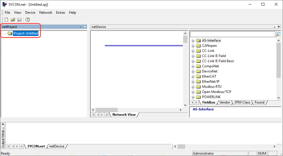
- Start the SYCON.net software.
- If necessary, skip the prompt for an administrator password when starting the software for the first time.
- Save the new project under a suitable name.
- Click the project in the netProject section.
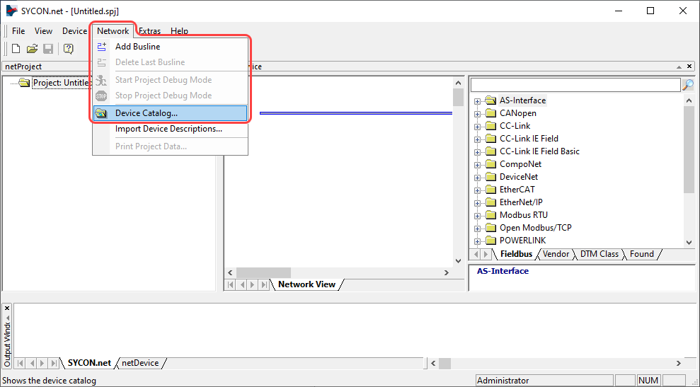
- From the Network drop-down menu, choose Device Catalog....
- In the dialog that opens, click the Reload Catalog button.
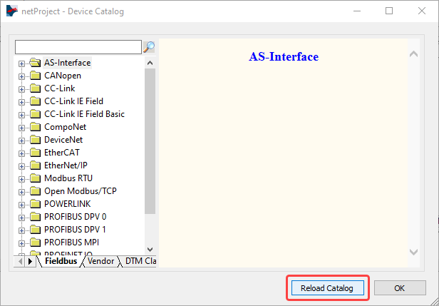
↪ The Device Catalog updates with previously installed device descriptions. - Click OK to close the dialog.
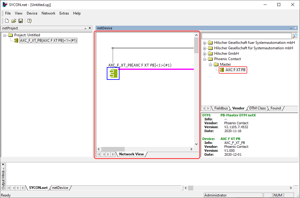
- In the netDevice window, click the Vendor tab under the right section.
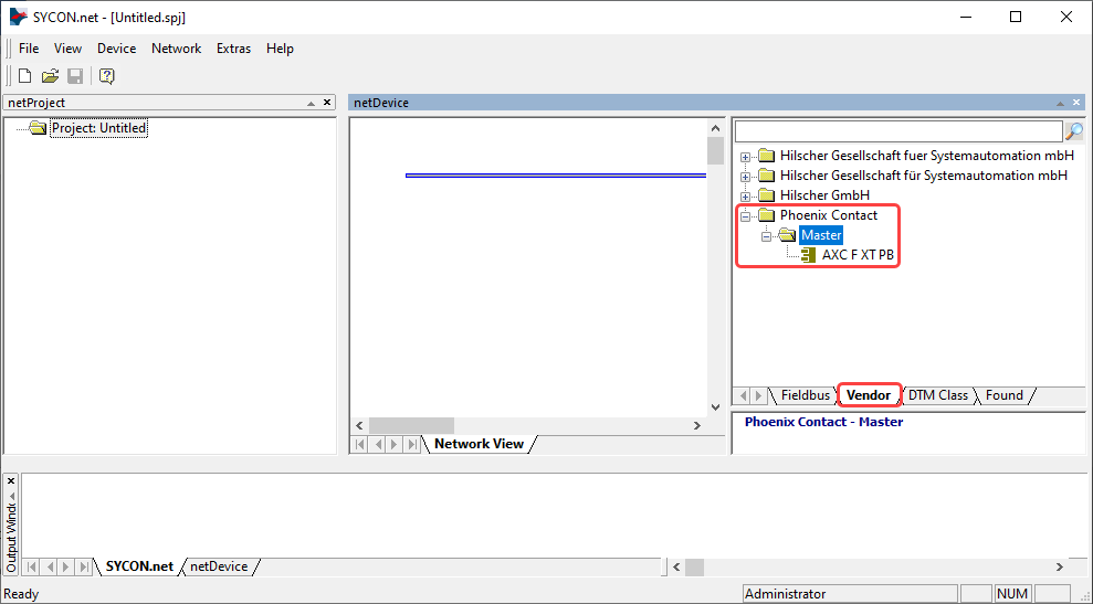
- Open the Phoenix Contact node, then the Master node.
- Drag-and-drop the AXC F XT PB master to the beginning of the horizontal pink line in the Network View section:
- Adding PROFIBUS devices
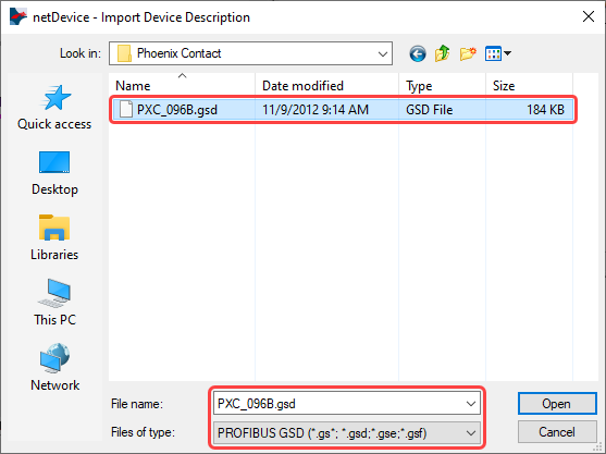
- From the Network drop-down menu, choose Import Device Descriptions....

- In the dialog that opens, navigate to the directory with your device description files.
- Select a .gsd file (e. g., PXC_096B.gsd for the IL PB BK DI8 DO4‑PAC Inline bus coupler), then click Open to start the import.
- If SYCON.net asks you if you want to reload the device catalog, confirm with Yes.
↪ The device is added to the structure in the Device Catalog, and (if it is not another master) put into a new Slave subfolder.
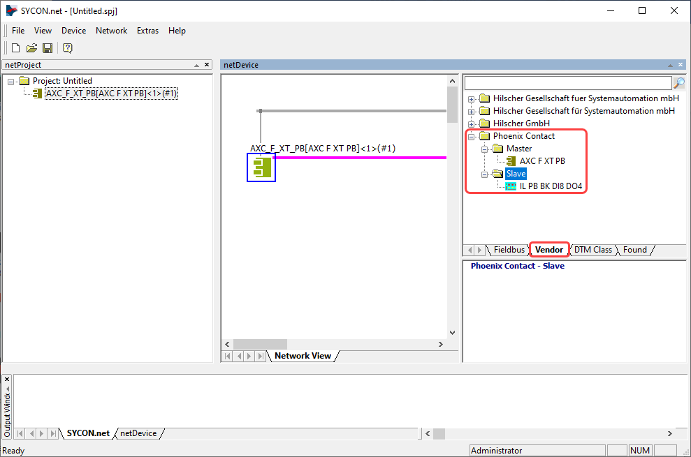
- Drag-and-drop the device you just added from the node in the right section to the middle section, at the pink line right beside the AXC F XT PB master.
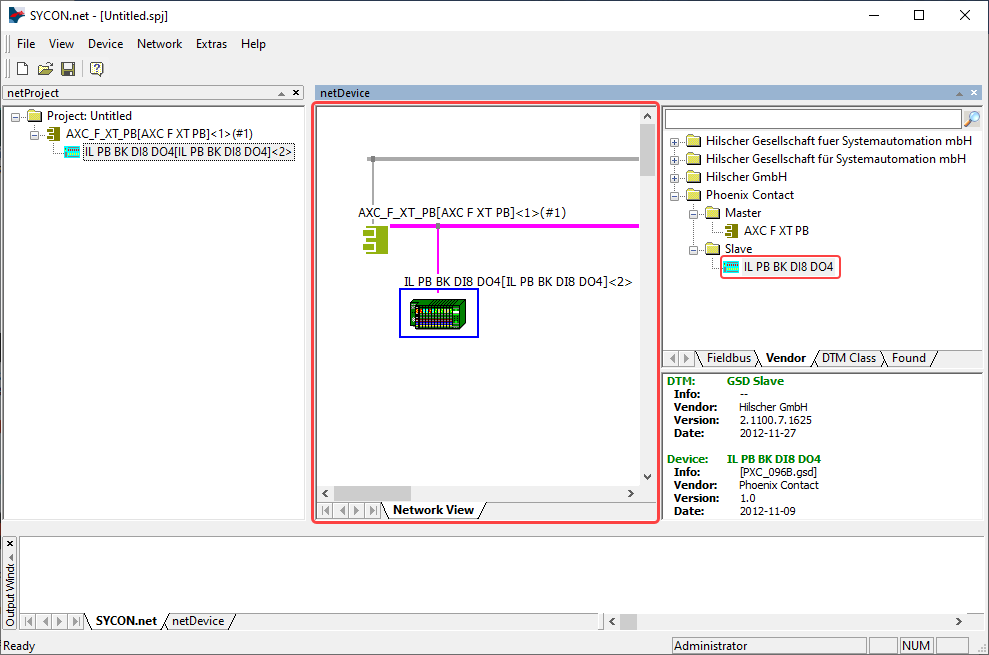
- Repeat the previous steps for each additional PROFIBUS device until the configuration is complete.
Note: If you want to use the I/Os of previously inserted PROFIBUS devices, add these I/Os for each PROFIBUS device one after the other.
Show an exampleShow an example
The following example shows how to proceed for the IL PB BK DI8 DO4 bus coupler.
- Double-click on IL PB BK DI8 DO4 in the Network View window.
→ The netDevice - Configuration dialog opens.
Note: Because the IL PB BK DI8 DO4 bus coupler has onboard I/Os, the BK: DI8 DO4 (8Bit) is already preset in the netDevice - Configuration dialog. When selecting the I/O modules observe the slot order.
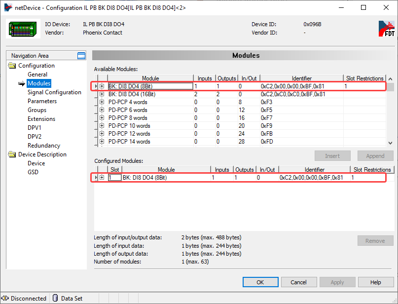
- Select the I/O modules according to your application by double-clicking on Available Modules.
- Click OK to accept your selection and to close the dialog.
- Repeat the previous steps for each additional PROFIBUS device.
- Double-click on IL PB BK DI8 DO4 in the Network View window.
- From the Network drop-down menu, choose Import Device Descriptions....
- Exporting the PLCnext Engineer library from SYCON.net
- Click Additional Functions / Export PLCnext Engineer Library in the context menu of the AXC F XT PB master.
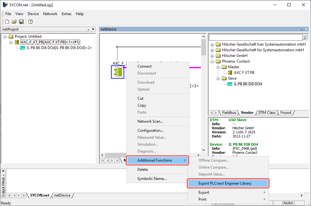
- Click OK when the Information dialog appears with the message The export succesfully completed!.
↪ The PLCnext Engineer library file Arp.Io.Profibus.pcwlx was exported to the directory C:\Users\Public\Public Documents\PLCnext Engineer\Libraries. - Exit SYCON.net.
- Click Additional Functions / Export PLCnext Engineer Library in the context menu of the AXC F XT PB master.
Programming the PROFIBUS station
- Importing the PROFIBUS configuration in your PLCnext Engineer project
- Start PLCnext Engineer and open an existing project, or create a new one (in this example with the AXC F 2152).
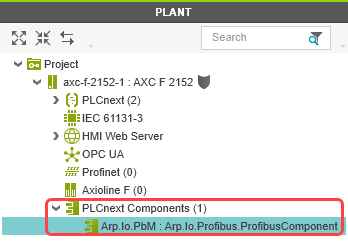
- Insert the Arp.Io.Profibus into PLCnext Engineer library into the COMPONENTS area as usually.
↪ The Arp.Io.Profibus library will now be displayed in the Libraries (x) section of the COMPONENTS area.
↪ The Arp.Io.PbM : Arp.Io.Profibus.ProfibusComponent will now be displayed under the PLCnext Components (x) node in the PLANT area.
- Assigning process data of the AXC F XT PB PROFIBUS master
- Double-click on Arp.Io.PbM : Arp.Io.Profibus.ProfibusComponent in the PLANT area.
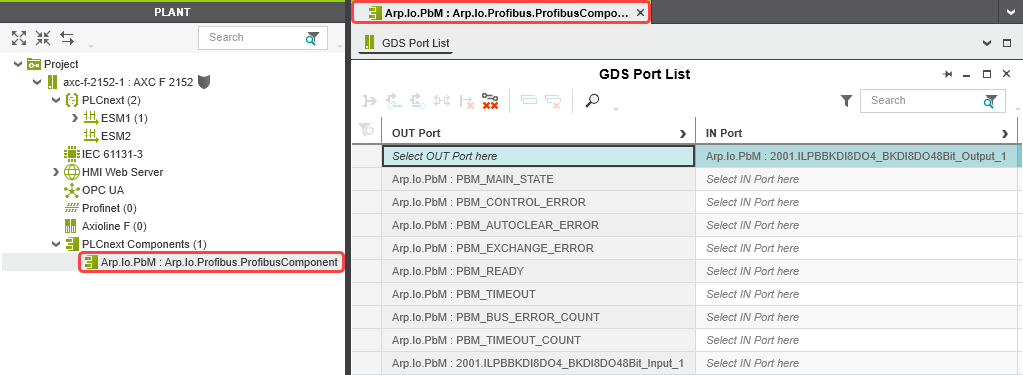
↪ The Arp.Io.PbM : Arp.Io.Profibus.ProfibusComponent editor opens, showing all variables of your AXC F XT PB PROFIBUS master.Note: When assigning the process data of the PROFIBUS master, the first PROFIBUS device after the PROFIBUS master will start with number 2001, and the second device will start with 3001. - To assign an IN port or an OUT port to a variable, click Select IN Port here or Select OUT Port here.
- Select the OUT ports and IN ports according to your application.
↪ The role picker opens. Note: Only the IN ports or the OUT ports that you can actually assign to the respective variable are displayed in the role picker.
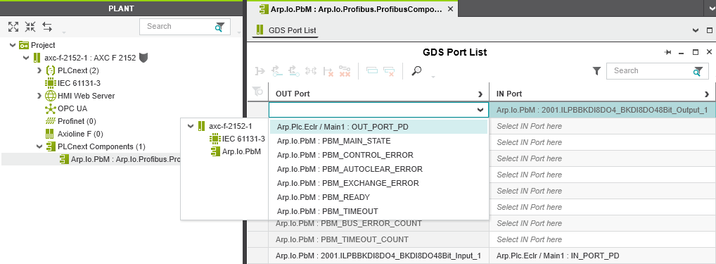
- In the role picker, select the IN ports or OUT ports that you want to assign to the respective variable.
- The IN port or the OUT port is assigned to the variable.
- Proceed as described above to add all variables to your application.
- Double-click on Arp.Io.PbM : Arp.Io.Profibus.ProfibusComponent in the PLANT area.
- Writing and starting the project
- Make sure, a firmware version ≥ 2022.0 LTS is installed on the AXC F 2152 controller.
- Double-click the controller node in the PLANT area.
- Select Write and Start Project in the controller cockpit.
↪ TheRUNLED lights up continuously when the AXC F XT PB PROFIBUS master was started properly.
That's it: Your AXC F XT PB is set up.