How to set up the AXC F XT ETH 1TX module
Available on AXC F 2152 from 2019.0 LTS, and on AXC F 3152 from 2021.0 LTS
AXC F 2152 or AXC F 3152 can be extended with an additional Ethernet interface using the AXC F XT ETH 1TX left-alignable Axioline F extension module. This topic shows how to integrate and configure the AXC F XT ETH 1TX.
Installing the AXC F XT ETH 1TX Ethernet interface
To install the extension module, see its package slip (coming with the product) or the data sheet.
Tutorial video
Note: Tutorial videos are embedded from the Phoenix Contact Technical Support YouTube channel. With playing an embedded YouTube video in this platform, you accept the YouTube Terms & Conditions.
Even showing the video previews on this page depends on your personal settings in the Cookie consent dialog. To watch YouTube videos, you have to allow cookies for marketing purposes which will remain on your device. The data gained through these cookies will be used by YouTube to provide video suggestions and advertisements based on your browsing habits, and may be made available to other parties.
| 10m:15s | HDTV 720p | English | English |
In this video, see how to integrate this module:
- 00m:00s - Understand what is it about
- 01m:24s - Mount the module
- 03m:58s - Configure the station in PLCnext Engineer
- 08m:18s - Check the configuration via WBM
Products used in this video:
- PLCnext Control AXC F 3152
- PLCnext Control AXC F 2152
- AXC BS L 2 bus base for left-aligning
(Note: sold separately, does not come with the PLCnext Control or the extension module!) - AXC F XT ETH 1TX
- PLCnext Engineer 2020.6
Integrating the AXC F XT ETH 1TX module in a PLCnext Engineer project
Requirements
- The AXC F XT ETH 1TX is installed and the supply voltage is connected (see AXC F XT ETH 1TX data sheet).
- In PLCnext Engineer:
- A project has been created
- The IP settings have been configured
- A connection to the controller has been established
Selecting the AXC F XT ETH 1TX Ethernet interface
- Double-click the controller node in the PLANT area.
The controller editor group opens.
- Select the Settings editor.
- Select the Hardware extensions view.
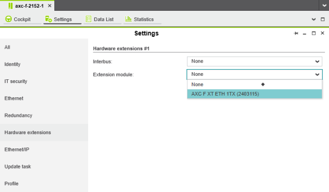
- From the Extension module drop-down list, select AXC F XT ETH 1TX (2403115).

Setting the IP address range
- Double-click the Project (x) node in the PLANT area.
The Project editor group opens.
- Select the Settings editor.
- Set the desired IP address range and the subnet mask for the project.
Note: The IP address range must differ from the IP address range that was originally set (see Setting the IP address range).
Setting the IP address
Once you have selected the AXC F XT ETH 1TX Ethernet interface as a hardware extension, you need to set the IP address of the Ethernet interface.
- Select the Ethernet view.

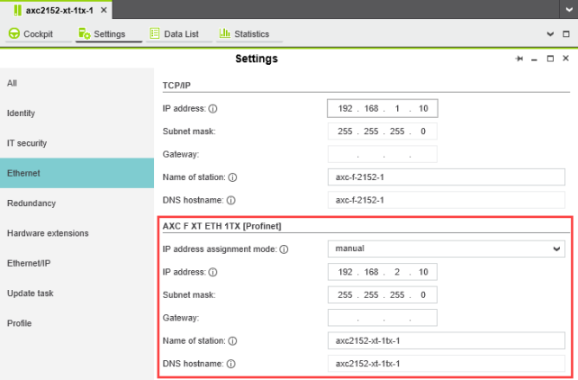
The IP address of the AXC F XT ETH 1TX Ethernet interface can be set automatically or manually.
The IP address is assigned to the Ethernet interface when you have connected PLCnext Engineer to the controller, see Connecting to the controller.
Setting the IP address of the added interface
Setting the IP address automatically
- In the AXC F XT ETH 1TX [Profinet] area, select automatic from the IP address assignment mode drop-down list.
PLCnext Engineer automatically assigns an IP address to the Ethernet interface from the set IP address range (see Setting the IP address range) as soon as a connection to the controller is established (see Connecting to the controller).
Setting the IP address manually
- In the AXC F XT ETH 1TX [Profinet] area, select manual from the IP address assignment mode drop-down list.
- Enter the IP address, subnet mask, and gateway in the respective input fields.
PLCnext Engineer assigns the manually set IP address to the Ethernet interface as soon as a connection to the controller has been established (see Connecting to the controller).
Now you're ready to use the additional Ethernet interface in your PLCnext Engineer project.