RFC 4072S
![]()
Risk of unauthorized access to devices
The safety controller RFC 4072S has a touch screen display and is used with an external SD card. This makes unencrypted information available. To prevent damage, data corruption, loss of data, or misuse of data due to authorized access, make sure that only authorized access is possible.
- Protect the interfaces by installing the devices in a control cabinet.
- Secure the control cabinet with a lock.
- Make sure that only authorized persons have access to the control cabinet key.
- Run cables in such a way that they are protected against unauthorized access.
There are different Ethernet and firewall configurations due to three Ethernet interfaces.
Connecting and operating elements
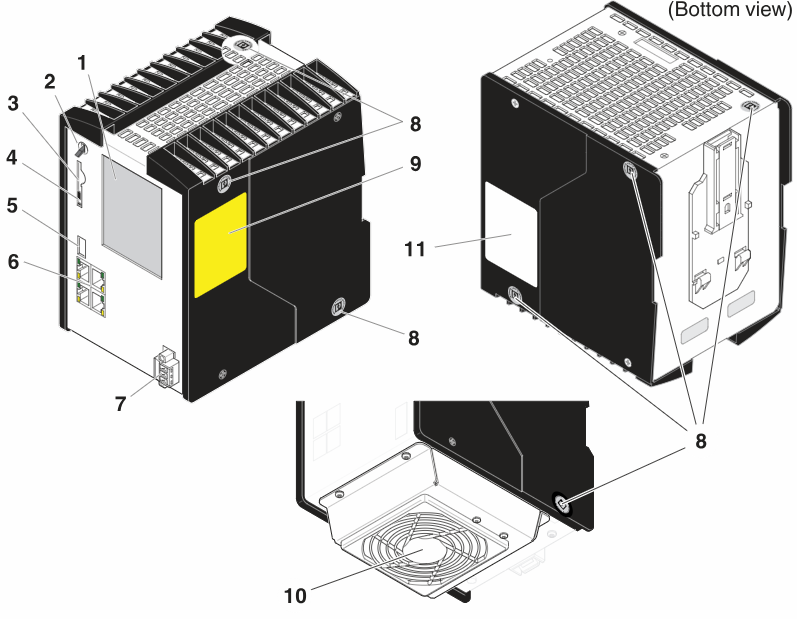
| 1 | Touch screen display |
| 2 | Mode selector switch |
| 3 | Slot for the parameterization memory/card holder (SD card) |
| 4 | Ejector for the parameterization memory |
| 5 | USB interface (type A USB 3.0 socket; currently not supported) |
| 6 | Ethernet interfaces (RJ45 sockets) |
| 7 | Connection for external supply voltage (24 V DC) |
| 8 | Security seals |
| 9 | Test marks and revision status (hardware/firmware of iSPNS 3000) |
| 10 | Fan module (optional) |
| 11 | Label showing:
|
Security seals
In order to prevent manipulation of the device supplied and to detect unauthorized opening of the device, security seals have been applied to the controller.
The housing of safety controller RFC 4072S is protected by security seals on both sides like shown below.
These security seals are damaged in the event of unauthorized opening. In this case, correct operation of the PLCnext Control can no longer be ensured.
- Check the delivery for transport damage. Damaged packaging is an indicator of potential damage to the device that may have occurred during transport. This could result in a malfunction.
- Do not open the housing. If the housing is opened, the function of the device can no longer be ensured.
- Check at regular intervals that none of the seals are damaged. If any of the seals are damaged or missing, it may be that the device has been tampered. In this case, contact Phoenix Contact without delay before using the device.
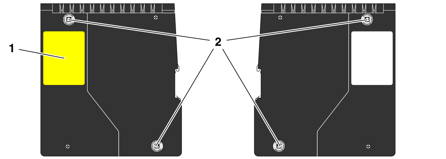
| 1 | Test marks and revision status (hardware/firmware) of the integrated safety-related PROFINET controller iSPNS 3000 |
| 2 | Security seals |
SD card
The use of the SD card is mandatory. You may only use encrypted SD cards (refer to the topic SD card encryption).
Phoenix Contact recommends the use of the following SD cards:
- SD FLASH 16GB PLCNEXT MEM LIC (item no. 1831737)
- SD FLASH 32GB PLCNEXT MEMORY LIC (item no. 1151111)
- SD FLASH PLCNEXT MEMORY LIC CFG (item no. 1308064)
- SD FLASH 8GB PLCNEXT MEMORY LIC (item no. 1151112) - discontinued
From firmware 2024.0 LTS, these special SD cards provide data protection, and therefore can be used together with the Security Profile.
Sensitive data is stored on the SD card. This data can even be restored after reformatting the SD card.
- To protect the data, make sure that the cover of the slot for the SD card is always screwed tight.
Touch screen display
The RFC 4072S has a touch screen display (also referred to as “display” in the following). This display shows tiles containing various information on the device and the connected network. The display allows you to retrieve information about the iSPNS 3000 and OPC UA connections, for example. The depth of information shown varies by tapping the individual tiles. The display allows menu-guided operation of the device. Among other things, you can reset the device to the factory default.
How to reset the controller
The menu MAINTENANCE allows for the following maintenance settings:
- PLC REBOOT:
Restarts the RFC 4072S - FACTORY RESET:
Resets the RFC 4072S to the factory defaults (Reset type 1)
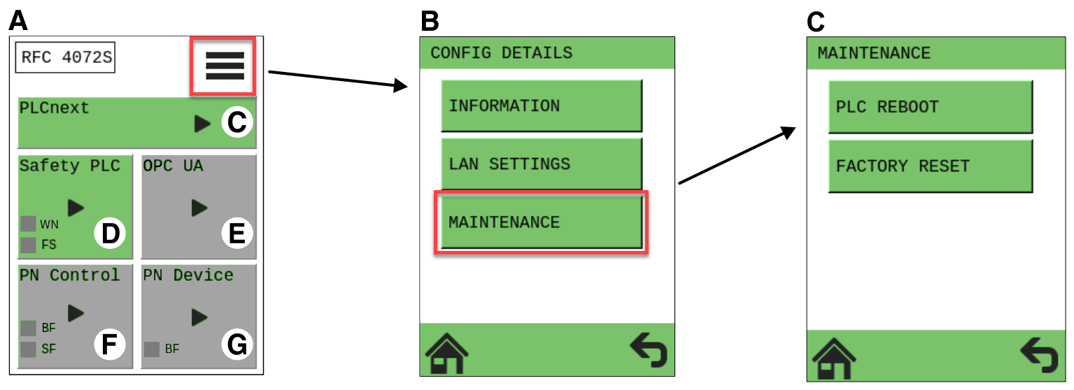
| A | Home menu |
| B | CONFIG DETAILS menu |
| C | MAINTENANCE menu |
Status information
There are status information on the touch screen display. The status information of the individual tiles of the display is only shown in the home menu. The background color on the individual tiles varies depending on the state.
Status information of the safety PLC (iSPNS 3000):
| Indicator | Color | Meaning |
| Gray | The function of the iSPNS 3000 is deactivated. No safety-related program is loaded. | |
 |
Blue |
Initial state in which the iSPNS 3000 passes through various phases until it is ready for operation (e.g., self-test, synchronization with the standard controller). The iSPNS 3000 is ready for operation once it has passed through these phases. FS (Failure State) is off. |
 |
Green |
Cyclical processing of the safety-related application program has started. FS (Failure State) is off. |
 |
Orange |
The iSPNS 3000 is in the "Debug Run" state. FS (Failure State) is off. |
 |
Orange |
The iSPNS 3000 is in the "Debug Stop" state. FS (Failure State) is off. |
 |
Red |
The iSPNS 3000 is in the safe state (failure state). FS (Failure State) is red. |
Diagnostic indicators
The diagnostic indicators of all the tiles are displayed in the home menu using virtual LEDs.
Below you can see the meaning of the FS (Failure State) LED (at the Safety PLC tile):
| LED | Color | Meaning | |
| FS | Red | On | A critical error has occurred and been detected. The iSPNS 3000 has switched to the "safe state". |
| Flashing 1 Hz |
|
||
| Gray | Off | Error-free operating state of the iSPNS 3000 (if supply voltage is present) | |
Booting the device
During boot, the USB interface is intentionally accessible via a connected keyboard.
You can choose between:
- Linux A
- Linux B
- Recovery
- Installing a new firmware via USB device
After the firmware has booted, the USB interface is disabled.

Risk of unauthorized access to the firmware of the device
Attackers can boot the device with a different firmware than intended if they have physical access to the device.
To prevent damage, data corruption, loss of data, or misuse of data due to authorized access, make sure that only authorized access is possible:
- Protect the interfaces by installing the device in a control cabinet.
- Secure the control cabinet with a lock.
- Make sure that only authorized persons have access to the control cabinet key.
- Make sure that on all possible boot partitions the intended firmware is installed before using the device for productive applications.
Assignment of the Ethernet interfaces
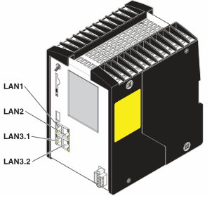
The following is an overview of how the Ethernet interfaces are assigned by default in the various pages in the WBM:
| Ethernet interface hardware | Description | PROFINET function by default | Ethernet interface WBM - Network page | Ethernet interfaces WBM - Firewall page |
| LAN1 | 10/100/1000 BASE-T(X), separate MAC address |
PROFINET Controller | TCP/IP (LAN1) | enp1s0 |
| LAN2 | 10/100/1000 BASE-T(X), separate MAC address |
TCP/IP (LAN2) | enp2s0 | |
| LAN3.1 | 10/100/1000 BASE-T(X), common MAC address, internally switched |
PROFINET Device | TCP/IP (LAN3) - Switched Mode | enp6s0 |
| LAN3.2 |
Activating PROFINET and OPC UA®
After you have performed a threat analysis and implemented appropriate protective measures from the security context, you can activate PROFINET Controller on the System services page (System → System services) in the WBM.
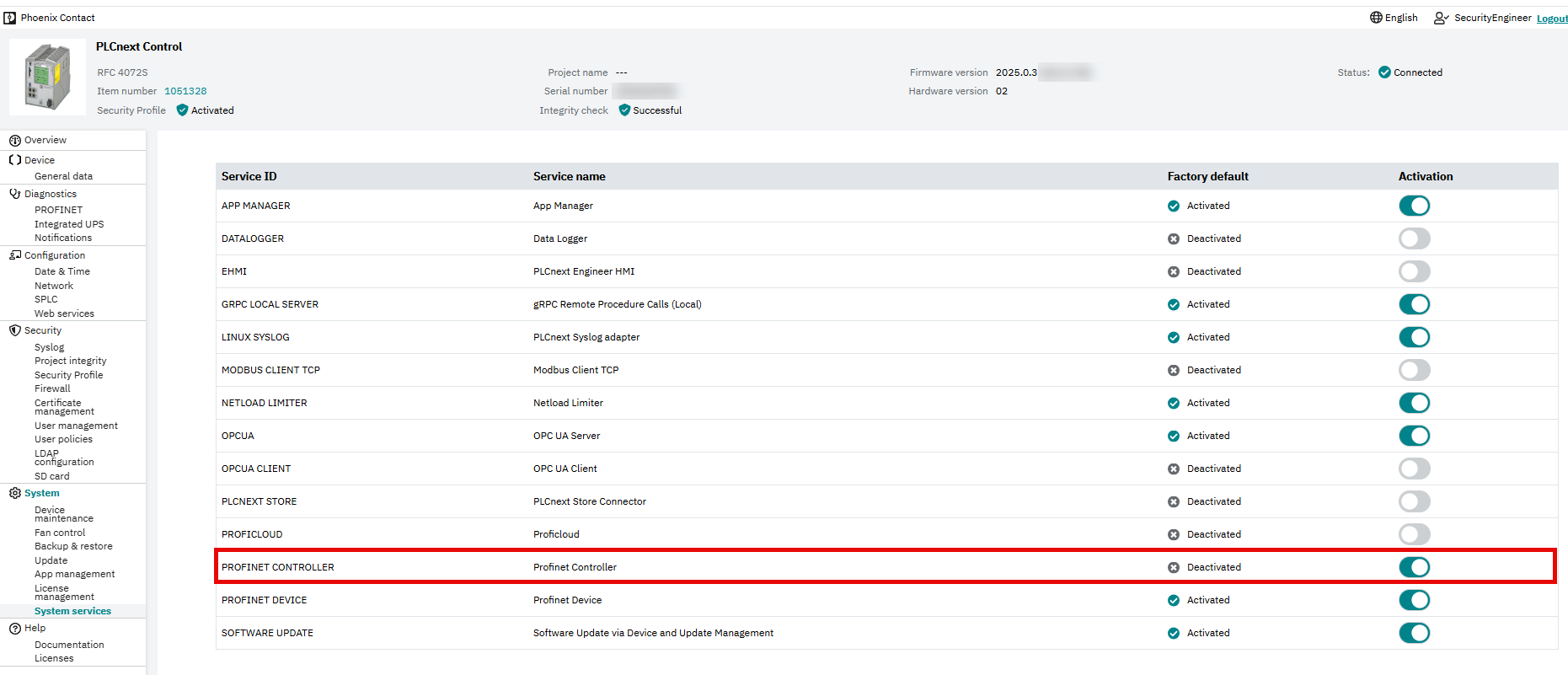
![]() For further information on how to activate PROFINET, refer to the topic Activating PROFINET® in this PLCnext Technology ‑ Security Info Center.
For further information on how to activate PROFINET, refer to the topic Activating PROFINET® in this PLCnext Technology ‑ Security Info Center.
![]() For further information on PROFINET in the WBM, refer to the PROFINET diagnostics topic in the main PLCnext Technology ‑ Info Center.
For further information on PROFINET in the WBM, refer to the PROFINET diagnostics topic in the main PLCnext Technology ‑ Info Center.
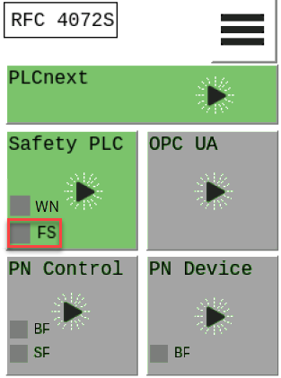
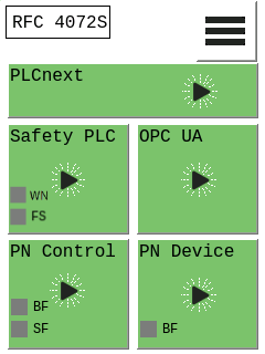
After activation of PROFINET, the home display looks like this:
Using PROFINET
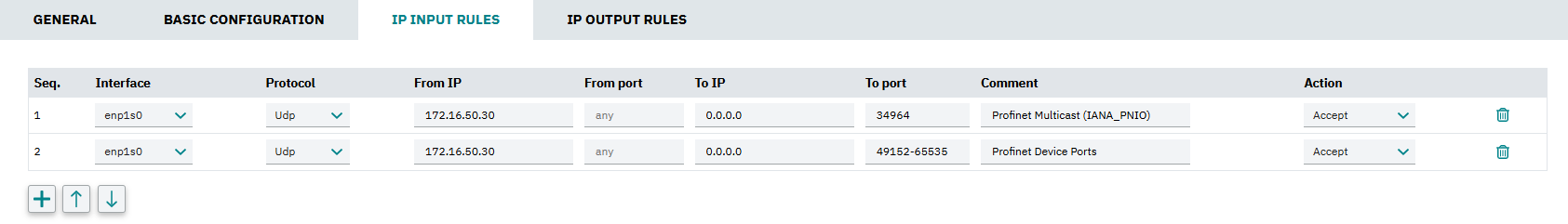
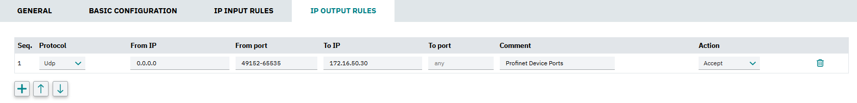
You need to adjust the firewall configurations (for more information, refer to the firewall basic configurations ):
Mode selector switch
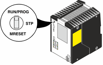
The mode selector switch is used to define the operating state of the standard controller only. The mode selector switch does not influence the operating state of the safety-related PROFINET controller (SPNS).
There are three operating modes: The RUN/PROG and STP (= stop) positions have a toggle-button function, and the MRESET position has a push-button function. After releasing the switch in the MRESET position, it returns to the STP position.
![]() For further information on the mode selector switch, refer to the user manual for RFC 4072S controllers.
For further information on the mode selector switch, refer to the user manual for RFC 4072S controllers.
Netload Limiter configuration
You configure the Netload Limiter on the Netload Limiter page in the WBM (Configuration → Network, Netload Limiter tab).
For further information, refer to the topic Configuring Netload Limiter.
Controller-specific information on the 62443-4-2 compliance list