Starting up INTERBUS with logical addressing
Available on AXC F 2152 and AXC F 3152 from firmware 2019.3, and PLCnext Engineer from 2022.0 LTS
Requirements
- The AXC F XT IB is installed and the supply voltage is connected (see AXC F XT IB data sheet).
- In PLCnext Engineer:
- A project has been created
- The IP settings have been configured
- A connection to the controller has been established
Adding the AXC F XT IB to your bus configuration
Selecting the AXC F XT IB
- Double-click the controller node in the PLANT area.
↪ The controller editor group opens. - Select the Settings editor.
- Select the Hardware extensions view.
- From the Interbus drop-down list, select AXC F XT IB logical addressing (2403018).
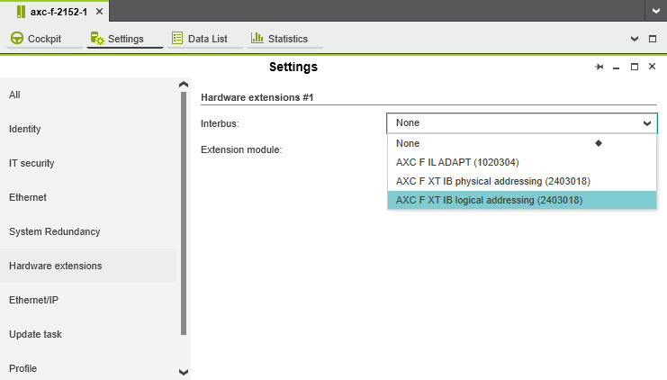
↪ The AXC F XT IB node is now displayed in the PLANT area.
 node in the PLANT area")
Adding necessary libraries
- In the COMPONENTS area, open the Libraries (x) section.
- Right-click Libraries (x).
- From the context menu, select Add Library....

- In the file explorer that opens, select the Inline library and the PLCnext Controller library (by pressing Ctrl).
Note: If you have created the project with a project template, the PLCnext Controller library is already added by default. - Click the Open button.
↪ The two libraries are now displayed in the Libraries (x) section in the COMPONENTS area.
Adding a bus coupler
- In the PLANT area, double-click the AXC F XT IB node.
↪ The AXC F XT IB editor group opens. - Select the Device List editor.
- Click Select type here in the first row of the Device List editor.
↪ The Role Picker opens.
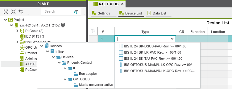
Note: Only those elements from the COMPONENTS area that you can actually use are displayed in the Role Picker. - Select the relevant bus coupler in the Role Picker.
↪ The bus coupler is added and mapped under the AXC F XT IB (X) node in the PLANT area.

- To add more bus couplers, proceed as described above.
Adding I/O modules
Once you have added all the bus couplers from your bus configuration to the project, you can add the I/O modules connected to each bus coupler.
- In the PLANT area, double-click the bus coupler to which you want to add I/O modules.
↪ The editor group for the selected bus coupler opens (in the example: il‑bk‑1). - Select the Module List editor.
- Click Select type here in the first row of the Module List editor.
↪ The Role Picker opens. Only those elements from the COMPONENTS area that you can actually use are displayed in the Role Picker.
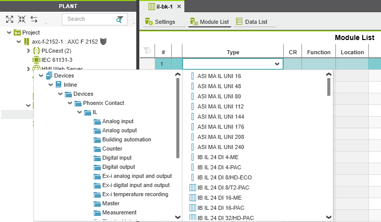
- Select the relevant I/O module in the Role Picker.
↪ The I/O module is added and shown in the PLANT area under the AXC F XT IB (X) node for the respective bus coupler.
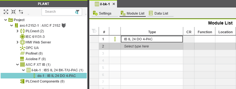
- To add more I/O modules, proceed as described above.
Completing the setup
To complete the setup of the AXC F XT IB, proceed with the instructions in the following topics:
- Programming in accordance with IEC 61131-3
- Instantiating a program
- Assigning process data
- Transferring a project to the controller
• Published/reviewed: 2026-05-11 ✿ Revision 094 •