Starting up INTERBUS with physical addressing
Available on AXC F 2152 and AXC F 3152 from firmware 2019.3, and PLCnext Engineer from 2019.3
Requirements
- The AXC F XT IB is installed and the supply voltage is connected (see AXC F XT IB data sheet).
- In PLCnext Engineer:
- A project has been created
- The IP settings have been configured
- A connection to the controller has been established
Adding the AXC F XT IB to your bus configuration
Selecting the AXC F XT IB
- Double-click the controller node in the PLANT area.
The controller editor group opens.
- Select the Settings editor.
- Select the Hardware extensions view.
- From the Interbus drop-down list, select AXC F XT IB physical addressing (2403018) (in PLCnext Engineer versions < 2022.0 LTS: AXC F XT IB (2403018).
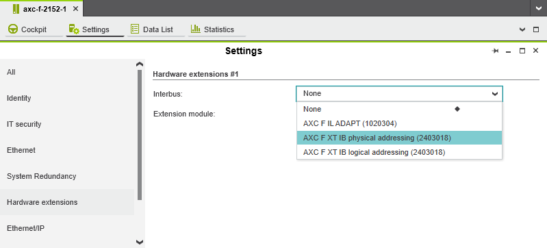
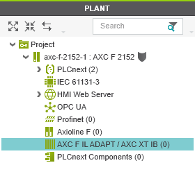
The AXC F IL ADAPT / AXC F XT IB (x) node is now displayed in the PLANT area.
Adding necessary libraries
- In the COMPONENTS area, open the Libraries (x) section.
- Right-click Libraries (x).
- From the context menu, select Add Library....

- In the file explorer that opens, select the Interbus physical library and the PLCnext Controller library (by pressing Ctrl).
Note: If you have created the project with a project template, the PLCnext Controller library is already added by default. - Click the Open button.
The two libraries are now displayed in the Libraries (x) section in the COMPONENTS area.
Adding the IB 256 module
- In the PLANT area, double-click the AXC F IL ADAPT / AXC F XT IB (x) node.
The AXC F IL ADAPT / AXC F XT IB controller editor group opens.
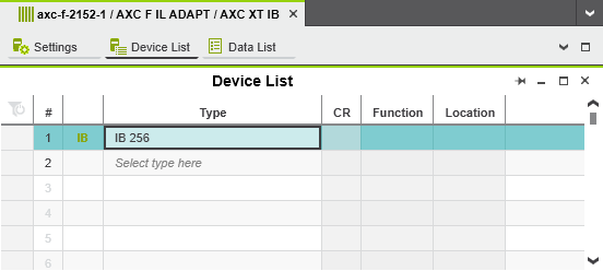
- Select the Device List editor.
- Click Select type here in the first row of the Device List editor.
The Role Picker opens.
- Select the IB 256 module in the Role Picker .
The IB 256 module is added and mapped under the AXC F IL ADAPT / AXC F XT IB (x) node in the PLANT area.
Starting up INTERBUS
Note: For starting up INTERBUS in the Structured Text (ST) programming language, the IB_CONTROL_NEXT function block is required.
The IB_CONTROL_NEXT function block sends G4 firmware services and receives the corresponding requested data.
Hide informationShow information on the IB_CONTROL_NEXT function block
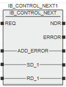
Inputs and outputs of the IB_CONTROL_NEXT function block:
| Name | Data type | Description |
| REQ | BOOL | The function block is started via a rising edge at this input. The function block is prepared for a restart via a falling edge at this input. |
| Name | Data type | Description |
| ADD_ERROR | ARRAY [2] OF WORD or ARRAY [4] OF BYTE |
An error has occurred. ADD_ERROR contains the corresponding error code. |
| SD_1 | ARRAY OF BYTE or ARRAY OF WORD |
Buffer for G4 firmware services to be sent (transmit buffer) |
| RD_1 | ARRAY OF BYTE or ARRAY OF WORD |
Buffer for received data (receive buffer) |
| Name | Data type | Description |
| NDR | BOOL | A rising edge indicates that new data has arrived in receive buffer RD_1. |
| ERROR | BOOL | TRUE: An error has occurred. The ADD_ERROR input/output provides error details FALSE: No error has occurred |
Creating data types
In order to handle INTERBUS process data, you need to create ARRAY data type fields.
- In the COMPONENTS area, open the Programming (x), Local (x), Data Types (x) section.
- Right-click to open the context menu and select Add Data Type Worksheet.
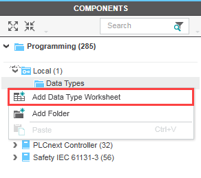
The data type worksheet is displayed in the Programming (x), Local (x), Data Types (x)section.
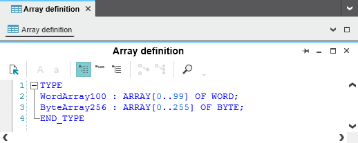
- Enter a unique and meaningful designation for the data type worksheet.
- Double-click to open the data type worksheet.
- Create the necessary data types.
Creating and opening a Program Organization Unit (POU)
Creating variables
For the example program in this topic, the following variables are used:
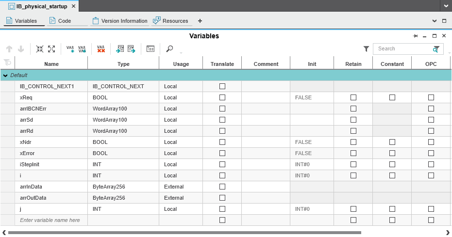
Close explanationShow explanation of the variables in the example program
| Variable | Data type | Use in the example program |
| IB_CONTROL_NEXT1 | IB_CONTROL_NEXT | Instantiation of the IB_CONTROL_NEXT function block |
| xReq | BOOL | At the REQ input of the IB_CONTROL_NEXT function block |
| arrIBCNErr | WordArray100 | At the ADD_ERROR input/output of the IB_CONTROL_NEXT function block |
| arrSd | WordArray100 | At the SD_1 input/output of the IB_CONTROL_NEXT function block |
| arrRd | WordArray100 | At the RD_1 input/output of the IB_CONTROL_NEXT function block |
| xNdr | BOOL | At the NDR output of the IB_CONTROL_NEXT function block |
| xError | BOOL | At the ERROR output of the IB_CONTROL_NEXT function block |
| iStepInit | INT | Specification of cases in the CASE instruction |
| i | INT | Iterator for FOR loop |
| arrInData [1] | ByteArray256 | For receiving INTERBUS process data |
| arrOutData [1] | ByteArray256 | For sending INTERBUS process data |
| j | INT | Iterator for IF condition |
- This variable must be created as an external variable or an IN/OUT port in PLCnext Engineer.
Creating a program
Adding worksheets
- Add all the necessary worksheets to the POU.
Recommended: To ensure the program is as clear as possible, create distinct code worksheets for the individual program components. Each worksheet is inserted in the POU editor group as an additional Code editor. Change the designation of each Code editor in order to clearly distinguish between the individual worksheets.
Programming INTERBUS startup
Note: Use Generation 4 (G4) INTERBUS firmware services for programming.
![]() For information on Generation 4 INTERBUS firmware services, please refer to the IBS SYS FW G4 UM E user manual. The user manual can be downloaded at the product page of the AXC F XT IB.
For information on Generation 4 INTERBUS firmware services, please refer to the IBS SYS FW G4 UM E user manual. The user manual can be downloaded at the product page of the AXC F XT IB.
The necessary programming steps to start up INTERBUS are:
- Instantiating the function block and assigning variables
- Executing the necessary G4 firmware services:
- Alarm_Stop (code:
1303hex) - Create_Configuration (code:
0710hex) - Start_Data_Transfer (code:
0701hex)
- Alarm_Stop (code:
Note: The example codes in the individual programming steps are extracts from the example program used in this topic. You cannot create an executable program using the example codes. The complete example program including CASE instructions can be found at the end of this section.
- Instantiating the function block and assigning variables
- Instantiate the IB_CONTROL_NEXT function block.
- Assign the corresponding variables to the inputs and outputs of the function block.
Example code snippet:
IB_CONTROL_NEXT1( REQ := xReq, ADD_ERROR := arrIBCNErr, SD_1 := arrSd, RD_1 := arrRd); xNdr := IB_CONTROL_NEXT1.NDR; xError := IB_CONTROL_NEXT1.ERROR; - Executing the necessary G4 firmware services
- Alarm_Stop (code:
1303hex)
Once you have instantiated the IB_CONTROL_NEXT function block and assigned the variables to the inputs/outputs, you need to reset INTERBUS:- Execute the "Alarm_Stop" G4 firmware service (code:
1303hex).Example code snippet:
arrSd[0] := WORD#16#1303; (* Write the “Alarm_Stop” service to the transmit buffer *) xReq := TRUE; (* Start function block (input REQ = TRUE) *) IF xNdr THEN (* Service has been executed *) xReq := FALSE; (* Stop function block *) IF arrRd[0] = WORD#16#9303 (* Alarm_Stop_Confirmation (code 9303hex) *) AND arrRd[1] = WORD#16#0001 (* Parameter_Count (code 0001hex) *) AND arrRd[2] = WORD#16#0000 THEN (* Result (code 0000hex) *) FOR i := 0 TO 99 DO arrRd[i] := WORD#16#0000; (* Delete receive buffer *) arrSd[i] := WORD#16#0000; (* Delete transmit buffer *) END_FOR END_IF; END_IF; - INTERBUS is in the READY state.
- Execute the "Alarm_Stop" G4 firmware service (code:
- Create_Configuration (code:
0710hex)
To start INTERBUS, you first need to create a valid configuration frame:- Execute the "Create_Configuration" G4 firmware service (code:
0710hex).Example code snippet:
arrSd[0] := WORD#16#0710; (* Write the “Create_Configuration” service to the transmit buffer *) arrSd[1] := WORD#16#0001; (* Parameter_Count (code 0001hex) *) arrSd[2] := WORD#16#0001; (* Frame_Reference of the configuration frame to be created *) xReq := TRUE; (* Start function block (input REQ = TRUE) *) IF xNdr THEN (* Service has been executed *) xReq := FALSE; (* Stop function block *) IF arrRd[0] = WORD#16#8710 (* Create_Configuration_Confirmation (code 8710hex) *) AND arrRd[1] = WORD#16#0001 (* Parameter_Count (code 0001hex) *) AND arrRd[2] = WORD#16#0000 THEN (* Result (code 0000hex) *) FOR i := 0 TO 99 DO arrRd[i] := WORD#16#0000; (* Delete receive buffer *) arrSd[i] := WORD#16#0000; (* Delete transmit buffer *) END_FOR END_IF; END_IF; - INTERBUS is in the ACTIVE state.
- Execute the "Create_Configuration" G4 firmware service (code:
- Start_Data_Transfer (code:
0701hex)
Once you have created a valid configuration frame, you can activate cyclic data transfer on INTERBUS and start INTERBUS:- Execute the "Start_Data_Transfer" G4 firmware service (code:
0701hex).Example code snippet:
arrSd[0] := WORD#16#0701; (* Write the “Start_Data_Transfer” service to the transmit buffer *)
xReq := TRUE; (* Start function block (input REQ = TRUE) *)
IF xNdr THEN (* Service has been executed *)
   xReq := FALSE; (* Stop function block *)
   IF arrRd[0]  = WORD#16#8701 (* Start_Data_Transfer_Confirmation (code 8701hex) *)
   AND arrRd[1] = WORD#16#0001 (* Parameter_Count (code 0001hex) *)
   AND arrRd[2] = WORD#16#0000 THEN (* Result (code 0000hex) *)
       FOR i := 0 TO 99 DO
           arrRd[i] := WORD#16#0000; (* Delete receive buffer *)
           arrSd[i] := WORD#16#0000; (* Delete transmit buffer *)
       END_FOR
   END_IF;
END_IF;
- Execute the "Start_Data_Transfer" G4 firmware service (code:
- Alarm_Stop (code:
Complete example program
If you use the example variables from this topic in your PLCnext Engineer project, you can use the following example program for INTERBUS startup.
- Copy the example program to the desired POU in your PLCnext Engineer project.
Close the exampleShow complete example program for INTERBUS startup
Complete example program:
IB_CONTROL_NEXT1(   REQ         := xReq,
                    ADD_ERROR   := arrIBCNErr,
                    SD_1        := arrSd,
                    RD_1        := arrRd);

xNdr    := IB_CONTROL_NEXT1.NDR;
xError  := IB_CONTROL_NEXT1.ERROR;
CASE iStepInit OF
(* Alarm_Stop (CODE 1303hex) *)
        0: arrSd[0] := WORD#16#1303;
           xReq    := TRUE;
           IF xNdr THEN
               xReq := FALSE;
               IF  arrRd[0] = WORD#16#9303
               AND arrRd[1] = WORD#16#0001
               AND arrRd[2] = WORD#16#0000 THEN
                   iStepInit := 10;
                   FOR i := 0 TO 99 DO
                       arrRd[i] := WORD#16#0000;
                       arrSd[i] := WORD#16#0000;
                   END_FOR
               ELSE
                   iStepInit := 1000;
               END_IF;
           END_IF;

(* Create_Configuration (CODE 0710hex) *)
        10: arrSd[0] := WORD#16#0710;
            arrSd[1] := WORD#16#0001;
            arrSd[2] := WORD#16#0001;
            xReq := TRUE;
            IF xNdr THEN
                xReq := FALSE;
                IF arrRd[0]  = WORD#16#8710
                AND arrRd[1] = WORD#16#0001
                AND arrRd[2] = WORD#16#0000 THEN
                    iStepInit := 20;
                    FOR i := 0 TO 99 DO
                        arrRd[i] := WORD#16#0000;
                        arrSd[i] := WORD#16#0000;
                    END_FOR
                ELSE
                    iStepInit := 1010;
                END_IF;
            END_IF;

(* Start_Data_Transfer (CODE 0701hex) *)
        20: arrSd[0] := WORD#16#0701;
            xReq := TRUE;
            IF xNdr THEN
                xReq := FALSE;
                IF arrRd[0]  = WORD#16#8701
                AND arrRd[1] = WORD#16#0001
                AND arrRd[2] = WORD#16#0000 THEN
                    iStepInit := 30;
                    FOR i := 0 TO 99 DO
                        arrRd[i] := WORD#16#0000;
                        arrSd[i] := WORD#16#0000;
                    END_FOR
                ELSE
                    iStepInit := 1020;
                END_IF;
            END_IF;
        END_CASE;
Assigning process data
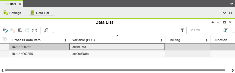
To send and receive INTERBUS process data, you first need to assign a variable of type byte array or word array to the input process data and the output process data of the IB 256 module:
- In the PLANT area, double-click the ib-1 : IB 256 node.
The IB-1 module editor group opens.
- Select the Data List editor.
You can see the process data items of the IB 256 module in the Data List editor.
- Assign the corresponding variable (byte array or word array) to all process data items of the IB 256 module:
- Click Select Variable (PLC) here in the row of the desired process data item in the Variable (PLC) column.
- The Role Picker opens.
- Select the relevant variable in the Role Picker .
- The variable is assigned to the process data item.
Hide the assignmentShow the assignment for the example program
Note: If you have created the variables as IN or OUT port variables, the process data is not assigned in the Data List editor.
For IN or OUT port variables, you have to assign the process data in the GDS Port List editor.
Determining the location of the process data
Once you have assigned the process data, you need to determine the location of the input and/or output process data of each connected INTERBUS remote bus device in the corresponding byte or word array.
The location in the byte or word array depends on:
- The position of the relevant INTERBUS remote bus device in the bus configuration.
- The input and/or output process data width of the relevant INTERBUS remote bus device.
- Steadily work through the bus configuration from left to right for all INTERBUS remote bus devices.
- Determine the location of the input and/or output process data based on the position of each INTERBUS remote bus device in the bus configuration and the relevant process data width.
Note: The process data width of each INTERBUS remote bus device can be found in the device-specific data sheet which can be downloaded on the Phoenix Contact website.
The input and/or output process data of the INTERBUS remote bus devices is assigned to the byte or word arrays in ascending order based on the position of the INTERBUS remote bus device in the bus configuration (from left to right).
Hide the exampleShow an example

Explanation of the example bus configuration
| INTERBUS remote bus device in the bus configuration (from left to right) | Input process data width according to device-specific data sheet | Output process data width according to device-specific data sheet |
| IB IL 24 DO 4-PAC (item no. 2861276) | – | 4 bits |
| IB IL 24 DI 8-PAC (item no. 2861247) | 8 bits | – |
| IB IL 24 DO 8-PAC (item no. 2861289) | – | 8 bits |
| IB IL 24 DO 2-PAC (item no. 2861470) | – | 2 bits |
| IB IL 24 DI 8-PAC (item no. 2861247) | 8 bits | – |
| IB IL 24 DI 2-PAC (item no. 2861221) | 2 bits | – |
| IB IL AI 2/4-20-PAC (item no. 2862217) | 32 bits | 32 bits |
| IB IL AI 2/4-20-PAC (item no. 2862217) | 32 bits | 32 bits |
| IB IL AO 2/SF-PAC (item no. 2863083) | 32 bits | 32 bits |
| INTERBUS remote bus device in the bus configuration (from left to right) | Location of the input process data in the "arrInData" byte array | Location of the output process data in the "arrOutData" byte array |
| IB IL 24 DO 4-PAC (item no. 2861276) | – | arrOutData[0] + arrOutData[1](bits: 00000000 + 0000XXXX) |
| IB IL 24 DI 8-PAC (item no. 2861247) | arrInData[0] + arrInData[1](bits: 00000000 + XXXXXXXX) |
– |
| IB IL 24 DO 8-PAC (item no. 2861289) | – | arrOutData[2] + arrOutData[3](bits: 00000000 + XXXXXXXX) |
| IB IL 24 DO 2-PAC (item no. 2861470) | – | arrOutData[4] + arrOutData[5](bits: 00000000 + 000000XX) |
| IB IL 24 DI 8-PAC (item no. 2861247) | arrInData[2] + arrInData[3](bits: 00000000 + XXXXXXXX) |
– |
| IB IL 24 DI 2-PAC (item no. 2861221) | arrInData[4] + arrInData[5](bits: 00000000 + 000000XX) |
– |
| IB IL AI 2/4-20-PAC (item no. 2862217) | arrInData[6] + arrInData[7](bits: XXXXXXXX + XXXXXXXX)arrInData[8] + arrInData[9](bits: XXXXXXXX + XXXXXXXX)
|
arrOutData[6] + arrOutData[7](bits: XXXXXXXX + XXXXXXXX)arrOutData[8] + arrOutData[9](bits: XXXXXXXX + XXXXXXXX) |
| IB IL AI 2/4-20-PAC (item no. 2862217) | arrInData[10] + arrInData[11](bits: XXXXXXXX + XXXXXXXX)arrInData[12] + arrInData[13](bits: XXXXXXXX + XXXXXXXX)
|
arrOutData[10] + arrOutData[11](bits: XXXXXXXX + XXXXXXXX)arrOutData[12] + arrOutData[13](bits: XXXXXXXX + XXXXXXXX)
|
| IB IL AO 2/SF-PAC (item no. 2863083) | arrInData[14] + arrInData[15](bits: XXXXXXXX + XXXXXXXX)arrInData[16] + arrInData[17] (bits: XXXXXXXX + XXXXXXXX) |
arrOutData[14] + arrOutData[15](bits: XXXXXXXX + XXXXXXXX)arrOutData[16] + arrOutData[17](bits: XXXXXXXX + XXXXXXXX)
|
Hide the assignmentShow process data assignment to word arrays instead of byte arrays
| INTERBUS remote bus device in the bus configuration (from left to right) | Location of the process data in the word array at the RD_1 input/output | Location of the process data in the word array at the SD_1 input/output |
| IB IL 24 DO 4-PAC (item no. 2861276) | – | WORD 0 |
| IB IL 24 DI 8-PAC (item no. 2861247) | WORD 0 | – |
| IB IL 24 DO 8-PAC (item no. 2861289) | – | WORD 1 |
| IB IL 24 DO 2-PAC (item no. 2861470) | – | WORD 2 |
| IB IL 24 DI 8-PAC (item no. 2861247) | WORD 1 | – |
| IB IL 24 DI 2-PAC (item no. 2861221) | WORD 2 | – |
| IB IL AI 2/4-20-PAC (item no. 2862217) | WORD 3 WORD 4 |
WORD 3 WORD 4 |
| IB IL AI 2/4-20-PAC (item no. 2862217) | WORD 5 WORD 6 |
WORD 5 WORD 6 |
| IB IL AO 2/SF-PAC (item no. 2863083) | WORD 7 WORD 8 |
WORD 7 WORD 8 |
Creating the program
Once you have determined the location of the input and/or output process data of each connected INTERBUS remote bus device in the byte or word array, create the program:
Hide the exampleShow an example program
Example program with byte arrays: Writing output process data
| First INTERBUS remote bus device in the example bus configuration: IB IL 24 DO 4-PAC (item no. 2861276) Output process data length: |
IB IL 24 DO 4-PAC (item no. 2861276) |
| Output process data length: | 4 bits |
| Location of the process data: | arrOutData[0] + arrOutData[1] (bits: 00000000 + 0000XXXX) |
The output process data is in bits 1 ... 4 in the second element of the "arrOutData" byte array.
Example code for writing bits 1 ... 4 of the IB IL 24 DO 4-PAC INTERBUS remote bus device:
IF j < 15 THEN
    arrOutData[1] := TO_BYTE(j);
    j := j + 1;
ELSE
    j := 0;
END_IF;
Result: The 4 bits to be written are incremented by variable j. This means that the relevant bit is set in the second element of the "arrOutData" byte array. The corresponding LEDs on the INTERBUS remote bus device light up one after the other creating a running light.
The IB 256 module expects a word or byte array as the transfer value. In the example, a byte array is used. Since variable j is an INT-type variable, the integer value needs to be converted accordingly. The TO_BYTE function is used for this.
Reading input process data
To read input process data, the IB 256 module also expects a word or byte array as the transfer value. For the example in this topic, the "arrInData" byte array is used.
Completing the setup
To complete the setup of the AXC F XT IB, proceed with the instructions in the following topics: