PLCnext Engineer user interface
General overview
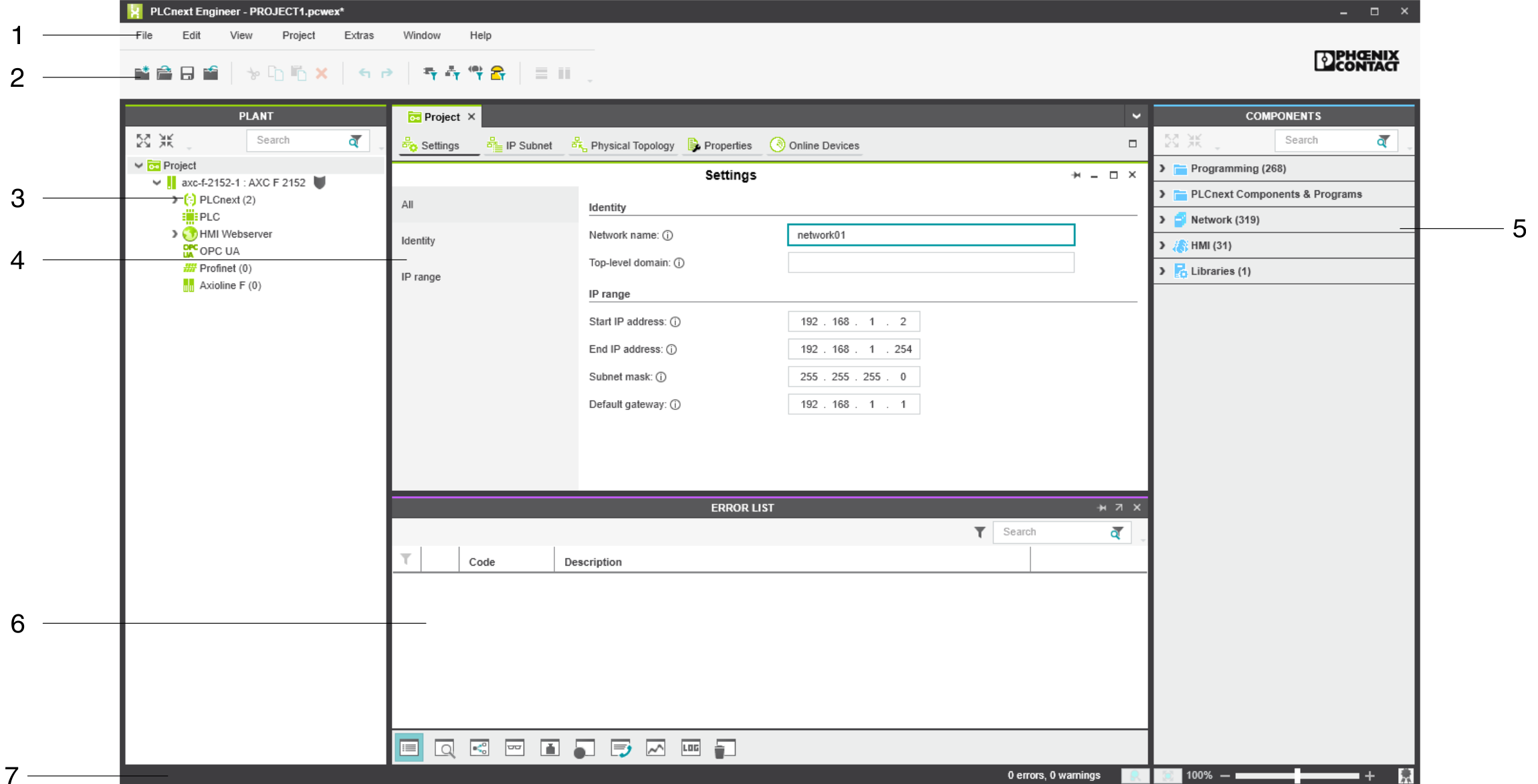
Key
- Menu bar
- Tool bar
- PLANT area
- Editors area
- COMPONENTS area
- Cross-functional area
- Status bar
PLANT area
All of the physical and logical components of your application are mapped in the form of a hierarchical tree structure in the PLANT area.

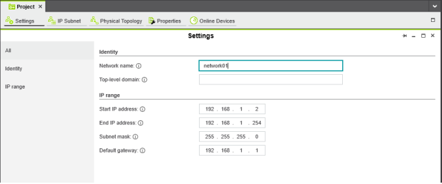
Editors area
Double-clicking on a node in the PLANT area or an element in the COMPONENTS area opens the associated editor group in the Editors area. Editor groups are always displayed in the center of the user interface. The color of the editor group indicates whether it is an instance editor (green; opened from the PLANT area) or a type editor (blue; opened from the COMPONENTS area). Each editor group contains several editors that can be opened and closed via buttons in the editor group.
In many editors, you can either display all information or filter out the relevant information. When the All view is selected, all information will be displayed. Specific information is indicated using the corresponding views below it.
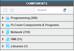
COMPONENTS area
The COMPONENTS area contains all of the components available for the project. The components can be divided into the following types based on their function:
- Developing program code (Data Types, Programs, and Functions & Function Blocks)
- Displaying all devices available for the PLANT area and adding them via GSDML or FDCML (Devices)
- Editing HMI pages (HMI)
- Adding libraries such as firmware libraries, IEC user libraries or libraries provided by Phoenix Contact (References)
Cross-functional area
The cross-functional area contains functions that extend across the entire project.
- ERROR LIST:
Shows all errors, warnings, and messages for the current project. - GLOBAL FIND AND REPLACE:
Finds and replaces strings in the project. - CROSS REFERENCES:
Displays all cross-references within the project, for example, the use and declaration of all variable types or HMI tags. - WATCH WINDOWS:
Debug tool; shows the current values of the added variables in online mode. - BREAKPOINTS:
Debug tool for setting and resetting breakpoints when debugging within the application - CALL STACKS:
Debug tool that shows the order for calling up when executing the code and that contains commands for debugging with breakpoints - LOGIC ANALYSIS:
Records and visualizes variable values at runtime. - LOGGING:
Shows all errors, warnings, and messages. A distinction is made between online (messages regarding the runtime environment, as well as errors and warnings that concern online communication) and engineering (messages regarding software events, e.g., GSDML and FDCML files; not project-related). - RECYCLE BIN:
Elements that have recently been deleted from the PLANT or COMPONENTS areas are moved to the recycle bin. Deleted elements can be restored from here, if needed.

See Also
- Creating a new project
- Configuring the IP settings
- Connecting PLCnext Engineer to the controller
- Configuring Axioline F modules
- Configuring PROFINET devices
- Configuring PROFINET controller and device
- Programming in IEC 61131-3 languages
- Instantiating a program
- Assigning process data
- Specifying the refresh interval for Axioline F I/O data
- Transferring a project to the controller