

Introduction
Hello everyone, here is the second tutorial about the IEC61850 standard, to follow it correctly, I strongly advise you to read the first one because I start from its end to continue the engineering.
Here is the link: https://www.plcnext-community.net/en/hn-makers-blog/658-straton-introduction-tutorial-1-data-exchange-between-plcnext-engineer-and-straton.html
We are not going to go through the standard, so this tutorial is aimed at people who are familiar with it.
This article will focus on one of the two communication protocols, the MMS (Manufacturing Message Specification), of this standard and will detail how to program it on straton.
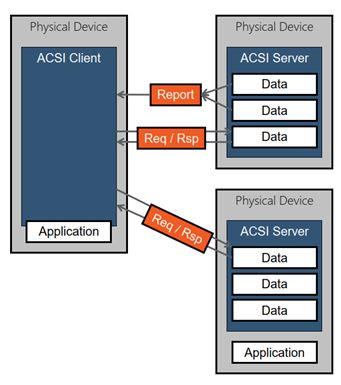
This protocol is used for modeling real devices and functions, for exchanging information and process data under real-time conditions. This communication is based on the client-server principle and takes place vertically in a network architecture.
There are two mechanisms in MMS :
- The Request-Reply mechanism: It is done at the beginning of the connection between the client and the server because the client needs to read the information before the connection is established. The client can then read, done by pooling, or write, by executing a command on the server.
- Reporting mechanism: The server sends data only when needed, defined by the user according to the application and the IEC61850 standard, frequently used for SCADA applications.
Tutorial 2 – MMS communication
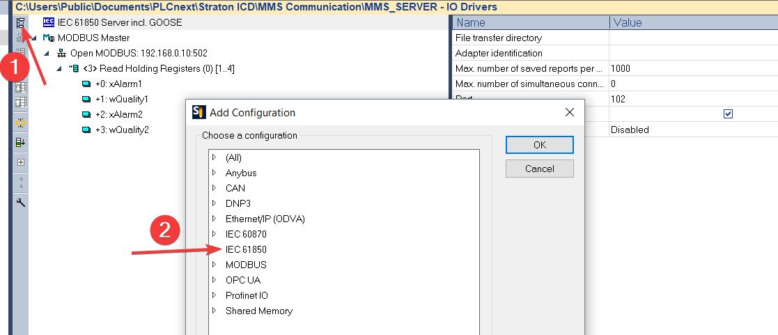
1) Now that the data exchange is configured between PLCNextEngineer and straton, it is necessary to insert an IEC61850 server in the fieldbus configuration. Click on “Insert Configuration” and choose the “IEC 61850 Server incl. GOOSE”. The standard defines TCP port number 102 for the MMS server role.
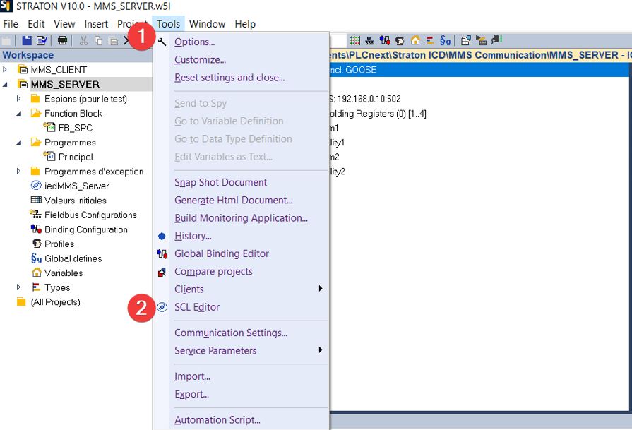
2) Now we can configure our Intelligent Electronic Device(IED) through the Substation Configuration description Language (SCL). To do this, open the SCL Editor by clicking on the Tools Tab.
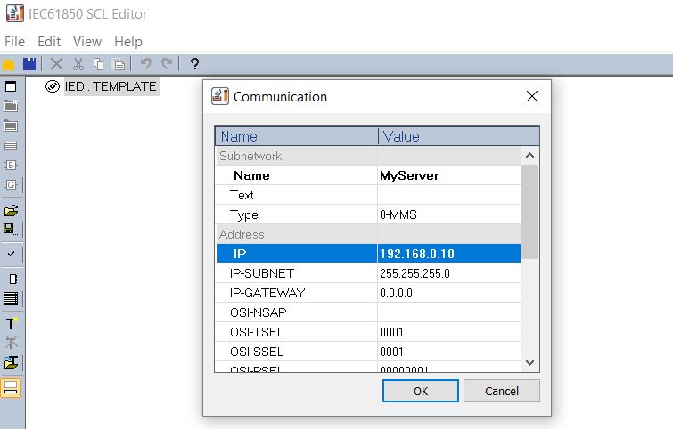
3) Doubble click on the IED in order to configure the communication part of the SCL.
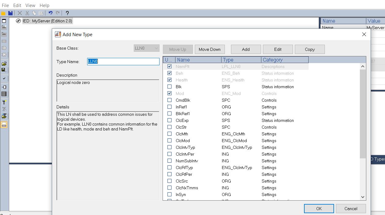
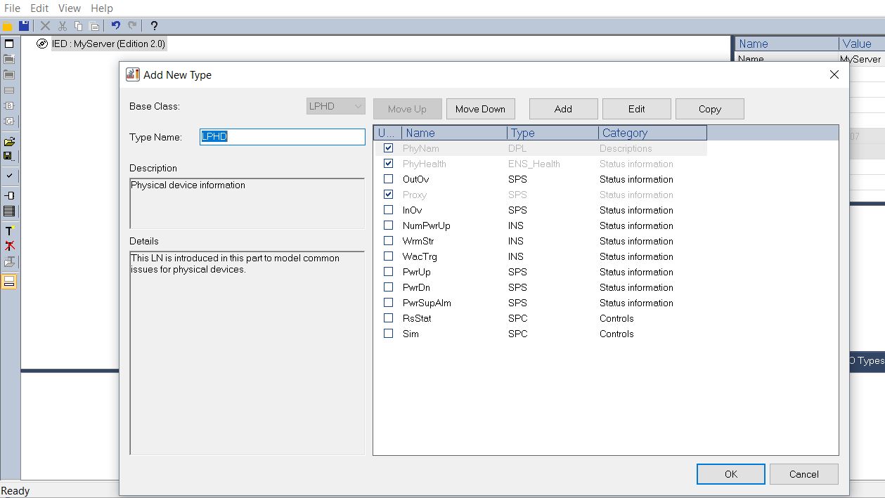
4) Then, add the two mandatory Logical Node, LLNO and LPHD. The default Data Objects are already selected, you are free to add more by clicking on the check boxes.
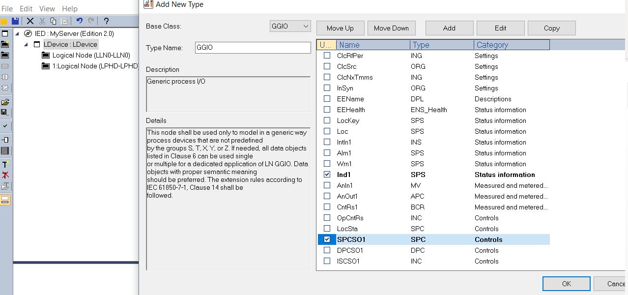
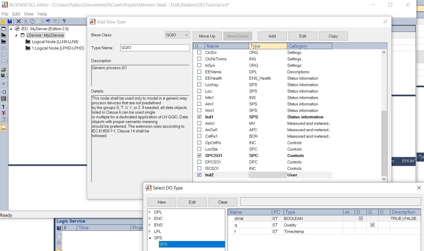
5) Now we are able to create your own Logical Node, which will contain the data you want to handle. Let’s create a GGIO which is a generic logical node. Since we have imported two alarms (BOOL) from PLCNextEngineer, let’s start by importing two SPS (Single Point Status) Data Objects and let’s take advantage of this to configure a SPC (Single Point Controllable) Data Object that will allow us to send commands from a client, planned for the 4th tutorial.
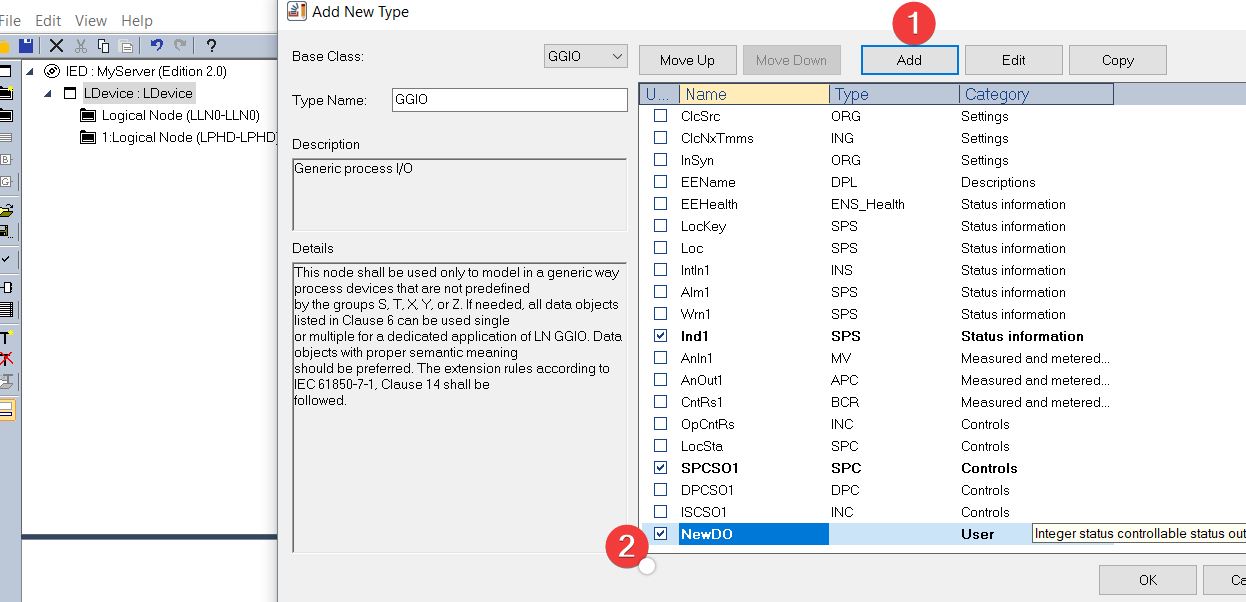
As you can see we have to create our own SPS for the second alarm.
We need to select the Data Attributes of the Data Object we have created (Ind2) i.e. stVal, q (quality) and t (timestamp).
Now we can configure the Data Attributes of our SPC so that we can use it in several types of commands.
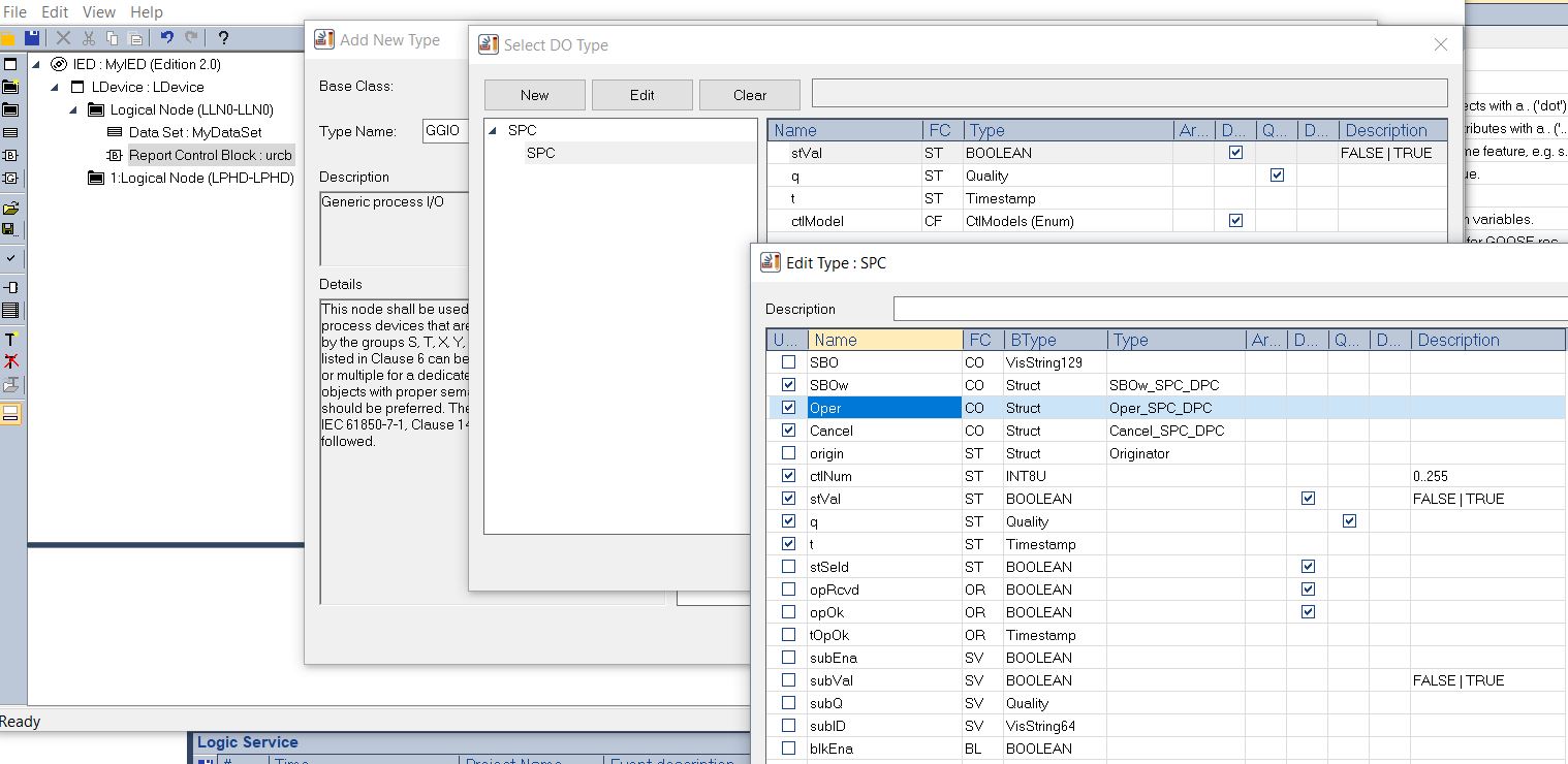
.
6) The next step is to add a Data Set which will contain the ordered group of references to Data Objects and/or Data Attributes contained in the data model and which will be shared with a 61850 client. As specified in the standard, the Data Sets are part of a logical node and most likely included in the LLN0.
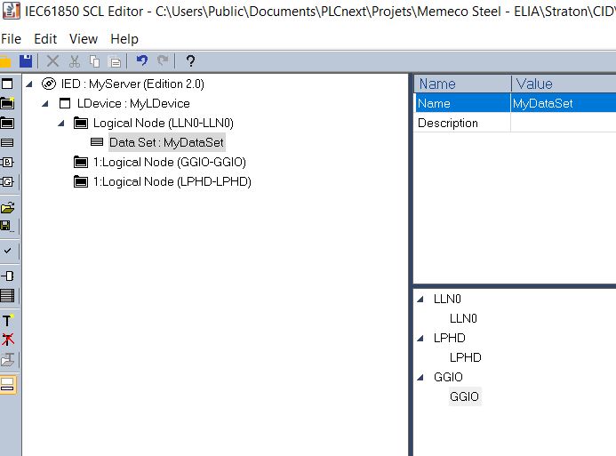
Double Click on it and select the appropriate data.
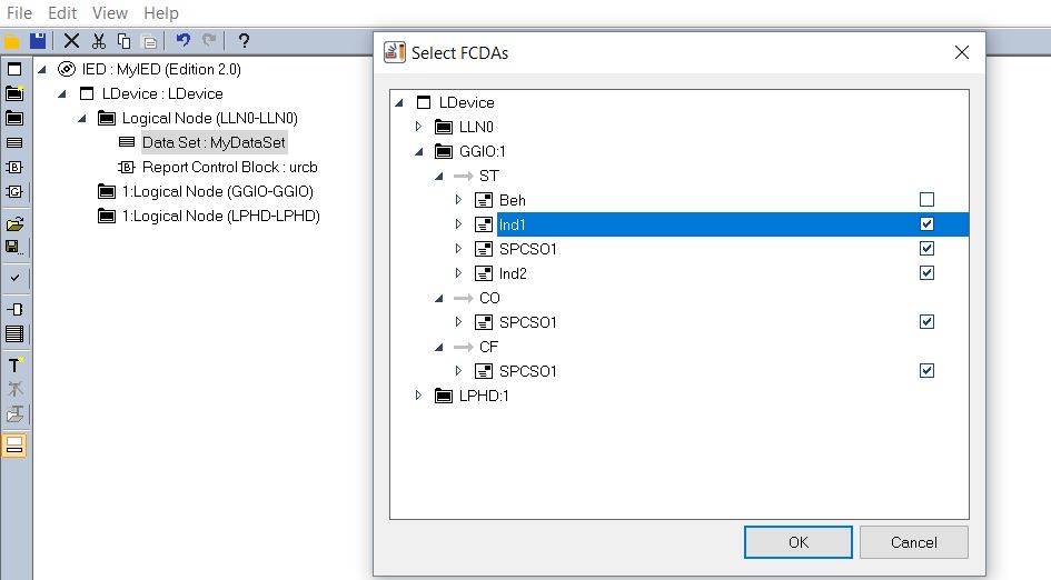
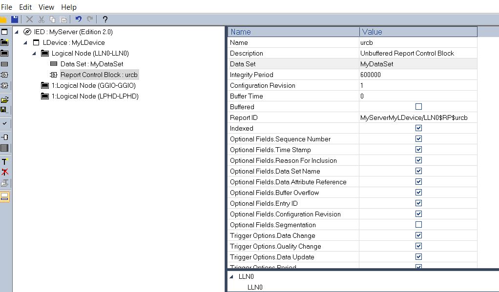
7) Finally we have to add a Report Control Block (RCB), then configure it by choosing its type and by linking it to the the Data Set and afterwards select the appropriate Optional Fields and Trigger Option.
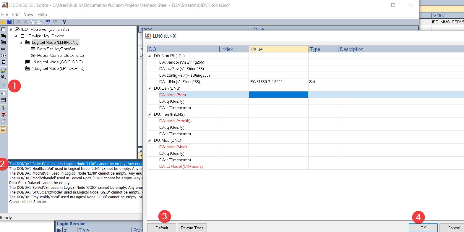
8) This tool is also equipped with a synthax checker. Click on it and the errors will appear in the log. Then click on these errors and press the default options until the message “Check succeeded” appears. Don’t forget to save your file in order to open it later.
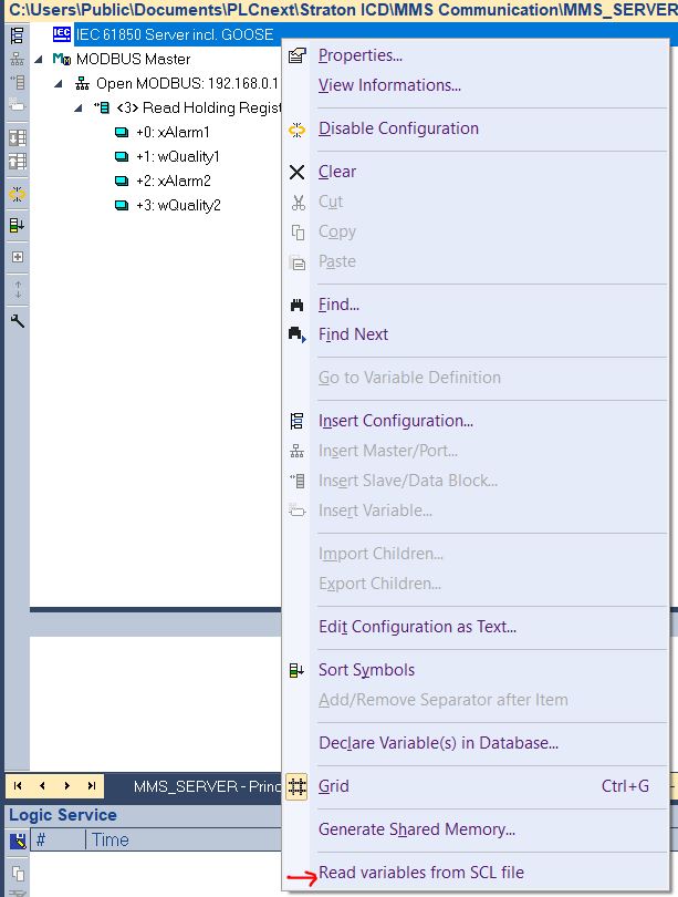
9) Our SCL is now ready to use. We have to import it into our main project by going in the Fieldbus Configuration and right click on IEC61850 Server incl. GOOSE. Then select the “Read variable from SCL file”.
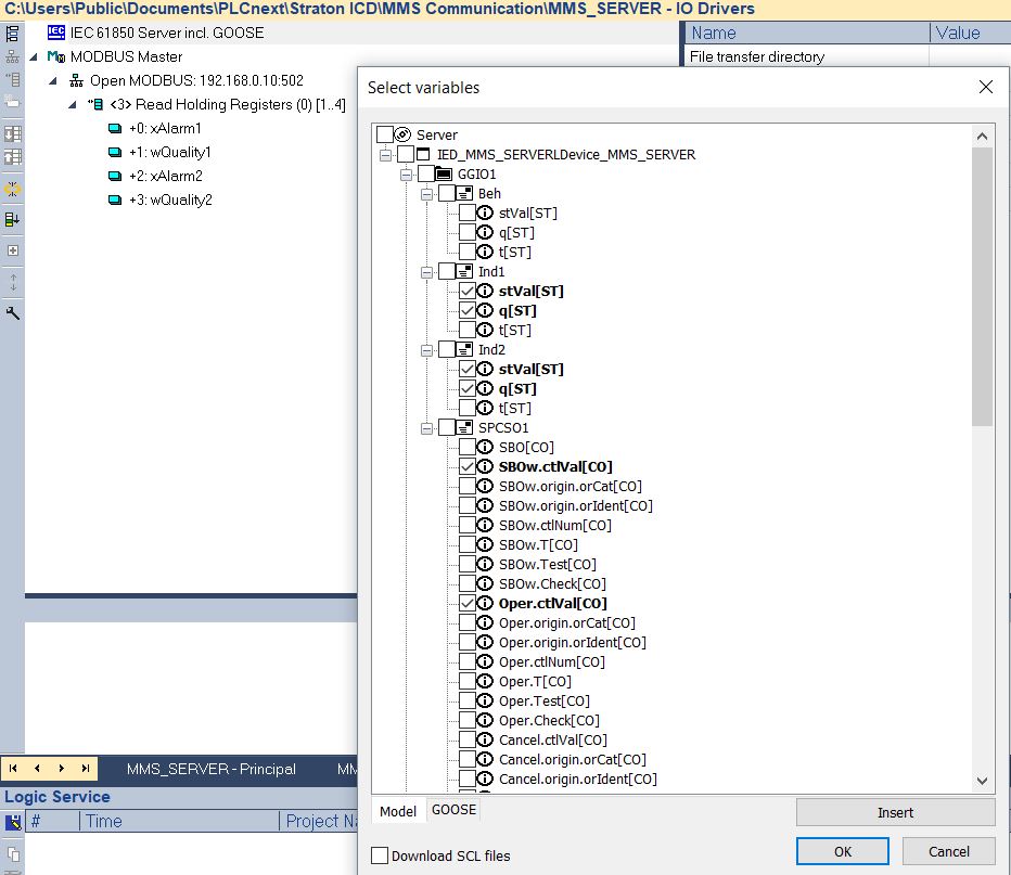
Click on “Insert” and import the SCL file you just create then select the Data Attributes of your Data Objects to be used as variables in the program. If you don’t select the timestamp, the runtime’s stack will handle it automatically.
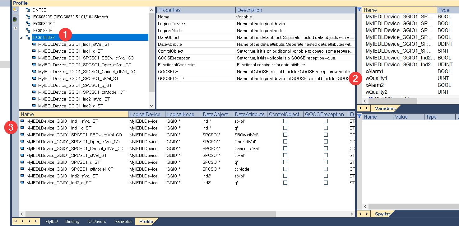
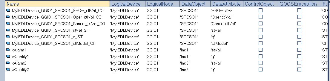
10) The last step is to map the PLCNext variables imported by MODBUS with the one created through the SCL. To do this, go to the “Profile” tab in the project tree, select IEC61850S2 and copy paste the name of the MODBUS variables into the “Name” column of the 61850 variables.
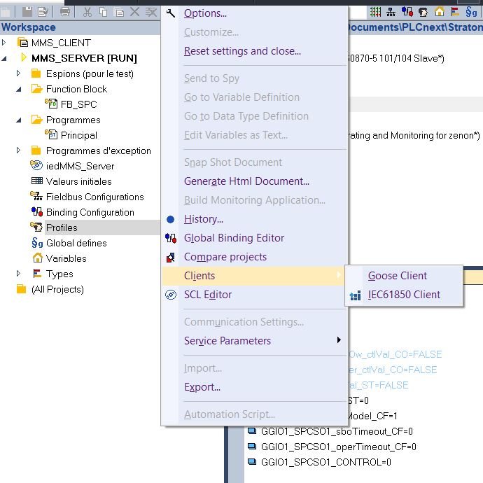
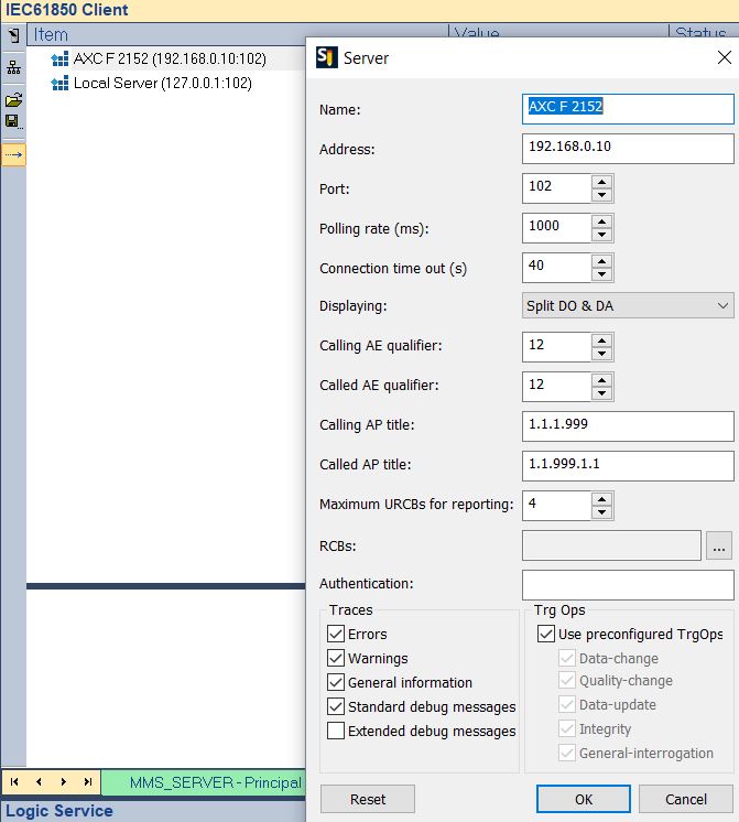
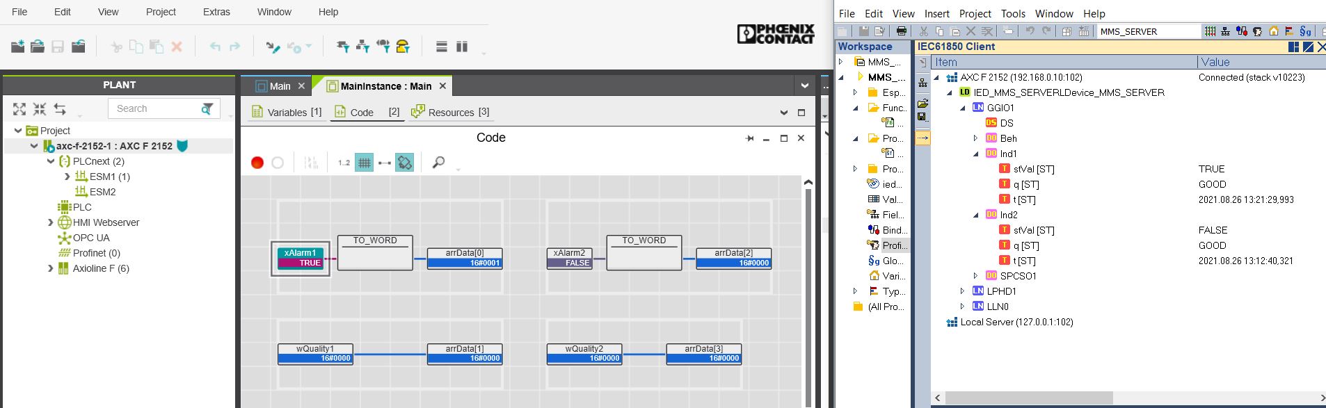
11) Now we will read online the 61850 server variables from a 61850 virtual client. straton Editor also has this tool, which is very easy to configure. You just have to configure the IP address to connect to. If you are familiar with IEDExplorer, it works just as well.
Now you can toggle the variable on PLCNextEngineer and see the effect from a 61850 client reading from a 61850 server.
Thanks for reading, the next tutorial is in progress.
Leave a Reply
You must be logged in to post a comment.