
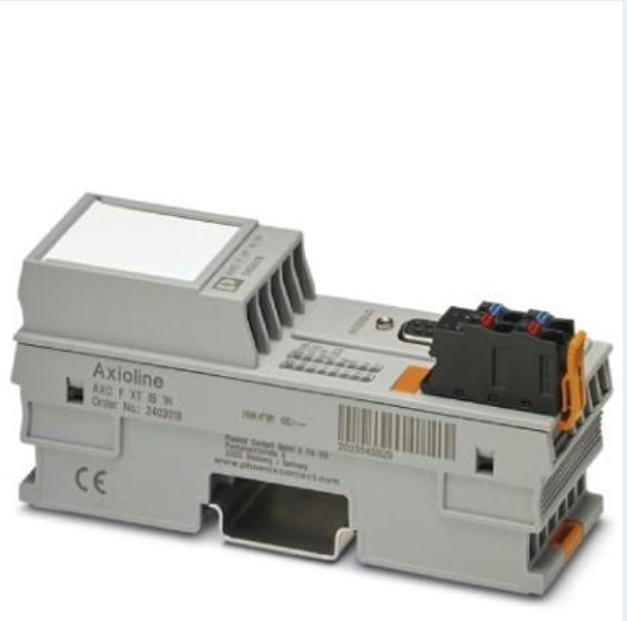
The AXC F XT IB ( article nr. 2403018) module is a left side connectable module for the AXC F 2152, that allows you to use interbus modules with the PLC next controller.
If you are interested I can provide you an example PLCnext project (see email link below this blog), this uses the ‘Auto Reading functionality’ to detect the modules that are connected on the interbus.
A certain amount of possible interbus modules is already integrated in the ‘Physical_IBS_ILC’ Function block, but further in this makersblog I will explain how you can add more interbus devices for your own project to this FB.
First off all you have to insert the module into your PLC next project:
This you can find in components searching for ‘IB 256’.
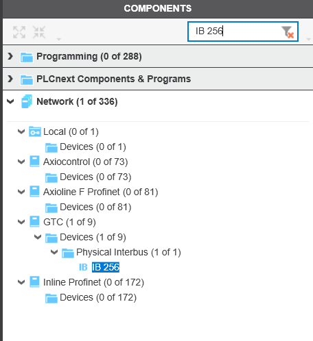
Drag and drop it under the Interbus folder in your Plant.
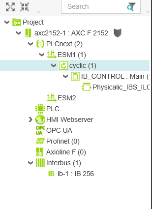
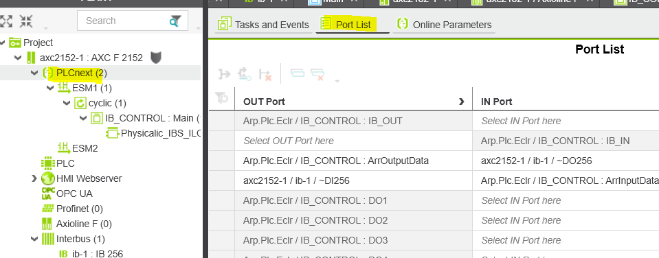
From this moment on only thing left to do is link the IN and OUT ports .
From Here on you are almost ready to really use your interbus modules.
Let’s have a look at where the ArrInputData and ArrOutputData are connected and how the ‘Auto Interbus reading’ really works + how to adapt it for your specific project / interbus module setup.
The linking of the Process Data (IN Port and OUT Port) is connected to the following FB used in the Main task.
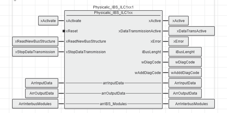
This block has a few interesting Inputs and outputs:
Inputs
xActivate : This will activate the FB, meaning he will read in the connected interbus modules and map the data into the arrIBS_Modules struct
xReset: This will reset the FB
xReadNewBusStructure: This will do a re ‘read’ action on the connected interbus modules
xStopDataTransmission: This will stop the Process data communication to the interbus modules
Outputs
xActive : Means the FB is active
xDataTransmissionActive: There is communication to the interbus
xError: The FB was not able to start up the interbus communication
iBusLenght: The amount of Interbus modules that the FB is able to see/work with
wDiagCode + wAddDiagCode : If issues on the interbus what is the possible cause
In-Outputs
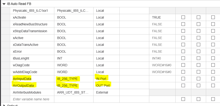
arrInputData : This is the IN-Port Process Data connection
arrOutputData : This is the OUT-Port Process Data connection
arrIBS_Modules : This gives you a struct with all the data comming from the Interbusmodules that are connected to the AXC F XT IB module.
The Struct i mentioned above looks like this:
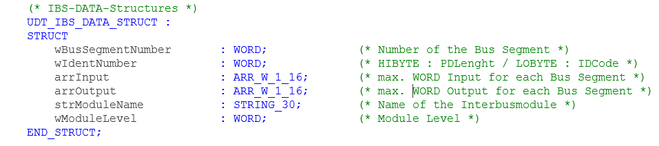
You see that this provides you all the needed information to further use the data into your own project.
Depending on the ID Code ( you find in the Low Byte of the wIdentNumber word) in combination with the PD Lenght (you find in the High Byte of this word) you know what interbusmodule it is .
arrInput and arrOutput give you the Process data of the module.
Bonus info “Next level” modification ? :
Adding more interbus modules to the Physical Interbus FB .
The FB consists of 3 code sheets: Interbus Handling/Read Inputs/Write Outputs
Interbus Handling code sheet:
Here you find starting from code line 158 the list of possible modules ( ID codes) the FB will understand. If you see that the interbus module you want to use is not in this list, feel free to add it in a similar way.
The case step indicates the ID code, the arrIBS_Modules[i].strModuleName will give you the string text you get in the arrIBS_Modules In/output Struct .
CASE iIDCode OF
(* Dampergate *)
3 : arrIBS_Modules[i].strModuleName := ‘Dampergate’;
(* RB-T Module *)
4 : arrIBS_Modules[i].strModuleName := ‘IB IL 24 RB-T ‘;
(* Lumgate Module *)
51 : arrIBS_Modules[i].strModuleName := ‘Lumgate ‘;
(* IB-IL-AO 2/U/BP *)
91 : arrIBS_Modules[i].strModuleName := ‘IB IL AO 2/U/BP’;
line 9 Read_Inputs
…..
Read Inputs code sheet:
Here you see starting from code line 9 , he checks for the ID codes to really execute some code or not. If you’re module(s) ID Code isn’t in here , feel free to add.
(* Mapping only for modules with Input data area *)
if ((iIDCode = 3) (* IBS-RL-24-DIO-8/8/8-R-LK-2MBD *)
or (iIDCode = 51) (* Lumgate *)
or (iIDCode = 91) (* IB-IL-AO 2/U/BP *)
or (iIDCode = 127) (* IB-IL-AI 2/SF *)
or (iIDCode = 190) (* IB-IL-24-DI *)
or (iIDCode = 191) (* PB data *)
or (iIDCode = 221)) (* PB diag *)
then
wRet := TO_Word (MEMORY_SET(iErr,UDINT#16#00,TO_BYTE (DINT#32),TO_UDINT(arrTempByte[1])));
xTest := True ;
(* Copy the input process data from the input array into temporary bytes *)
arrTempByte[1] := arrInputData[iActArrayPtr];
iActArrayPtr := iActArrayPtr + 1;
arrTempByte[2] := arrInputData[iActArrayPtr];
iActArrayPtr := iActArrayPtr + 1;
….
Additionally starting from line 218 you see a Case appear where the real linking is done to the Process Data from interbusmodules he detected by ID code + Process data length.
Depending on how long the process data is in amount of bytes you need to foresee that same amount in “arrTempByte(s)”, so here same story if you want to add your module if it’s not yet here , feel free to do so.
CASE iIDCode OF
3 :
CASE iPDLenght OF
(* BYTE-Module (2Bit, 4Bit, 8Bit) *)
2 : arrIBS_Modules[i].arrInput[1].B1 := arrTempByte[1];
arrIBS_Modules[i].arrInput[1].B0 := arrTempByte[2];
arrIBS_Modules[i].arrInput[2].B1 := arrTempByte[3];
arrIBS_Modules[i].arrInput[2].B0 := arrTempByte[4];
129: (* pijlkruis bord *)
arrIBS_Modules[i].arrInput[1].B1 := arrTempByte[1];
arrIBS_Modules[i].arrInput[1].B0 := arrTempByte[2];
arrIBS_Modules[i].arrInput[2].B1 := arrTempByte[3];
arrIBS_Modules[i].arrInput[2].B0 := arrTempByte[4];
……
Write Output code sheet:
This is then the stuff you need to do to link the process data to the interbusmodules.
Starting from code line 9 you find the following reference to check the ID code -> feel free to add your modules ID code if it’s not already in here
(* Mapping only for modules with Output data area *)
if ((iIDCode = 3) (* IBS-RL-24-DIO-8/8/8-R-LK-2MBD *)
or (iIDCode = 51) (* Lumgate *)
or (iIDCode = 91) (* IB-IL-AO 2/U/BP *)
or (iIDCode = 125) (* IB-IL-AO 1/SF *)
or (iIDCode = 127) (* IB-IL-AI 2/SF *)
or (iIDCode = 189) (* IB-IL-24-DO *)
or (iIDCode = 191) (* IB-IL-CNT *)
or (iIDCode = 221)) (* PB diag *)
then
…..
And last but not least starting from line 22 you’ll find the output process data linking , depending on ID code + PD lenght it is linked to the arrTempByte array.
Same here, if you want to add your own module feel free to integrate this here as well
CASE iIDCode OF
3 :
source code here
CASE iPDLenght OF
(* IB-IL-CNT *)
2 : arrTempByte[1] := arrIBS_Modules[i].arrOutput[1].B1;
arrTempByte[2] := arrIBS_Modules[i].arrOutput[1].B0;
arrTempByte[3] := arrIBS_Modules[i].arrOutput[2].B1;
arrTempByte[4] := arrIBS_Modules[i].arrOutput[2].B0;
(* pijlkruis bord *)
129 : arrTempByte[1] := arrIBS_Modules[i].arrOutput[1].B0;
arrTempByte[2] := arrIBS_Modules[i].arrOutput[1].B1;
arrTempByte[3] := arrIBS_Modules[i].arrOutput[2].B0;
arrTempByte[4] := arrIBS_Modules[i].arrOutput[2].B1;
arrTempByte[5] := arrIBS_Modules[i].arrOutput[3].B0;
arrTempByte[6] := arrIBS_Modules[i].arrOutput[3].B1;
…..
Example Project:
If you are interested to use/test this functionality please send me an email, this way I can provide you the example PLCnext project.
email: gwilde@phoenixcontact.be
Leave a Reply
You must be logged in to post a comment.